4 |
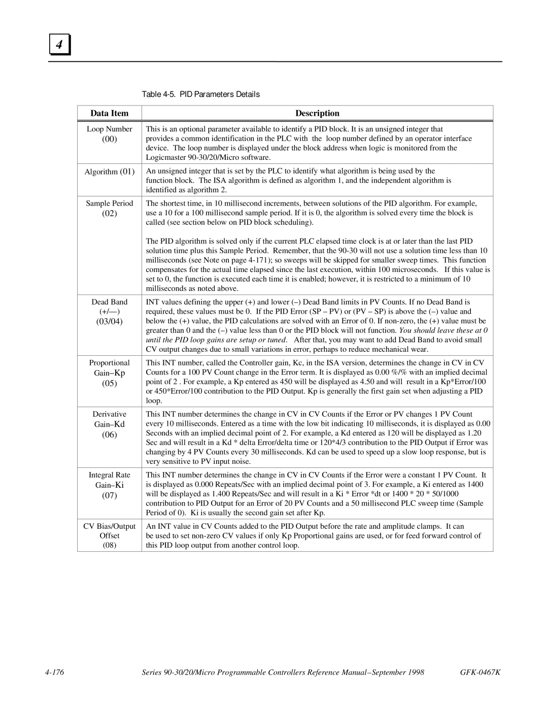
| Table |
|
|
Data Item | Description |
|
|
|
|
Loop Number | This is an optional parameter available to identify a PID block. It is an unsigned integer that |
(00) | provides a common identification in the PLC with the loop number defined by an operator interface |
| device. The loop number is displayed under the block address when logic is monitored from the |
| Logicmaster |
|
|
Algorithm (01) | An unsigned integer that is set by the PLC to identify what algorithm is being used by the |
| function block. The ISA algorithm is defined as algorithm 1, and the independent algorithm is |
| identified as algorithm 2. |
|
|
Sample Period | The shortest time, in 10 millisecond increments, between solutions of the PID algorithm. For example, |
(02) | use a 10 for a 100 millisecond sample period. If it is 0, the algorithm is solved every time the block is |
| called (see section below on PID block scheduling). |
| The PID algorithm is solved only if the current PLC elapsed time clock is at or later than the last PID |
| solution time plus this Sample Period. Remember, that the |
| milliseconds (see Note on page |
| compensates for the actual time elapsed since the last execution, within 100 microseconds. If this value is |
| set to 0, the function is executed each time it is enabled; however, it is restricted to a minimum of 10 |
| milliseconds as noted above. |
|
|
Dead Band | INT values defining the upper (+) and lower |
required, these values must be 0. If the PID Error (SP – PV) or (PV – SP) is above the | |
(03/04) | below the (+) value, the PID calculations are solved with an Error of 0. If |
| greater than 0 and the |
| until the PID loop gains are setup or tuned. After that, you may want to add Dead Band to avoid small |
| CV output changes due to small variations in error, perhaps to reduce mechanical wear. |
|
|
Proportional | This INT number, called the Controller gain, Kc, in the ISA version, determines the change in CV in CV |
Counts for a 100 PV Count change in the Error term. It is displayed as 0.00 %/% with an implied decimal | |
(05) | point of 2 . For example, a Kp entered as 450 will be displayed as 4.50 and will result in a Kp*Error/100 |
| or 450*Error/100 contribution to the PID Output. Kp is generally the first gain set when adjusting a PID |
| loop. |
|
|
Derivative | This INT number determines the change in CV in CV Counts if the Error or PV changes 1 PV Count |
every 10 milliseconds. Entered as a time with the low bit indicating 10 milliseconds, it is displayed as 0.00 | |
(06) | Seconds with an implied decimal point of 2. For example, a Kd entered as 120 will be displayed as 1.20 |
| Sec and will result in a Kd * delta Error/delta time or 120*4/3 contribution to the PID Output if Error was |
| changing by 4 PV Counts every 30 milliseconds. Kd can be used to speed up a slow loop response, but is |
| very sensitive to PV input noise. |
|
|
Integral Rate | This INT number determines the change in CV in CV Counts if the Error were a constant 1 PV Count. It |
is displayed as 0.000 Repeats/Sec with an implied decimal point of 3. For example, a Ki entered as 1400 | |
(07) | will be displayed as 1.400 Repeats/Sec and will result in a Ki * Error *dt or 1400 * 20 * 50/1000 |
| contribution to PID Output for an Error of 20 PV Counts and a 50 millisecond PLC sweep time (Sample |
| Period of 0). Ki is usually the second gain set after Kp. |
|
|
CV Bias/Output | An INT value in CV Counts added to the PID Output before the rate and amplitude clamps. It can |
Offset | be used to set |
(08) | this PID loop output from another control loop. |
|
|
Series |
