4 |
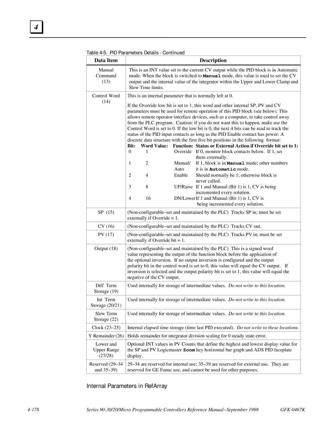
Table 4-5. PID Parameters Details - Continued
Data Item |
|
|
| Description |
|
|
| ||||
|
| ||||
Manual | This is an INT value set to the current CV output while the PID block is in Automatic | ||||
Command | mode. When the block is switched to Manual mode, this value is used to set the CV | ||||
(13) | output and the internal value of the integrator within the Upper and Lower Clamp and | ||||
| Slew Time limits. |
|
|
| |
|
| ||||
Control Word | This is an internal parameter that is normally left at 0. | ||||
(14) | If the Override low bit is set to 1, this word and other internal SP, PV and CV | ||||
| |||||
| parameters must be used for remote operation of this PID block (see below). This | ||||
| allows remote operator interface devices, such as a computer, to take control away | ||||
| from the PLC program. Caution: if you do not want this to happen, make use the | ||||
| Control Word is set to 0. If the low bit is 0, the next 4 bits can be read to track the | ||||
| status of the PID input contacts as long as the PID Enable contact has power. A | ||||
| discrete data structure with the first five bit positions in the following format: | ||||
| Bit: Word Value: Function: Status or External Action if Override bit set to 1: | ||||
| 0 | 1 | Override | If 0, monitor block contacts below. If 1, set | |
|
|
|
| them externally. |
|
| 1 | 2 | Manual/ | If 1, block is in Manual mode; other numbers | |
|
|
| Auto | it is in Automatic mode. | |
| 2 | 4 | Enable | Should normally be 1; otherwise block is | |
|
|
|
| never called. |
|
| 3 | 8 | UP/Raise | If 1 and Manual (Bit 1) is 1, CV is being | |
|
|
|
| incremented every solution. | |
| 4 | 16 | DN/LowerIf 1 and Manual (Bit 1) is 1, CV is | ||
|
|
|
| being incremented every solution. | |
|
|
| |||
SP (15) | Tracks SP in; must be set | ||||
| externally if Override = 1. |
|
| ||
|
|
| |||
CV (16) | Tracks CV out. | ||||
|
|
| |||
PV (17) | Tracks PV in; must be set | ||||
| externally if Override bit = 1. |
|
| ||
|
|
| |||
Output (18) | This is a signed word | ||||
| value representing the output of the function block before the application of | ||||
| the optional inversion. If no output inversion is configured and the output | ||||
| polarity bit in the control word is set to 0, this value will equal the CV output. If | ||||
| inversion is selected and the output polarity bit is set to 1, this value will equal the | ||||
| negative of the CV output. |
|
| ||
|
| ||||
Diff Term | Used internally for storage of intermediate values. Do not write to this location. | ||||
Storage (19) |
|
|
|
|
|
|
| ||||
Int Term | Used internally for storage of intermediate values. Do not write to this location. | ||||
Storage (20/21) |
|
|
|
|
|
|
| ||||
Slew Term | Used internally for storage of intermediate values. Do not write to this location. | ||||
Storage (22) |
|
|
|
|
|
|
| ||||
Clock | Internal elapsed time storage (time last PID executed). Do not write to these locations. | ||||
|
| ||||
Y Remainder (26) | Holds remainder for integrator division scaling for 0 steady state error. | ||||
|
| ||||
Lower and | Optional INT values in PV Counts that define the highest and lowest display value for | ||||
Upper Range | the SP and PV Logicmaster Zoom key horizontal bar graph and ADS PID faceplate | ||||
(27/28) | display. |
|
|
|
|
|
| ||||
Reserved | |||||
and | reserved for GE Fanuc use, and cannot be used for other purposes. | ||||
|
|
|
|
|
|
Internal Parameters in RefArray
Series |