4 |
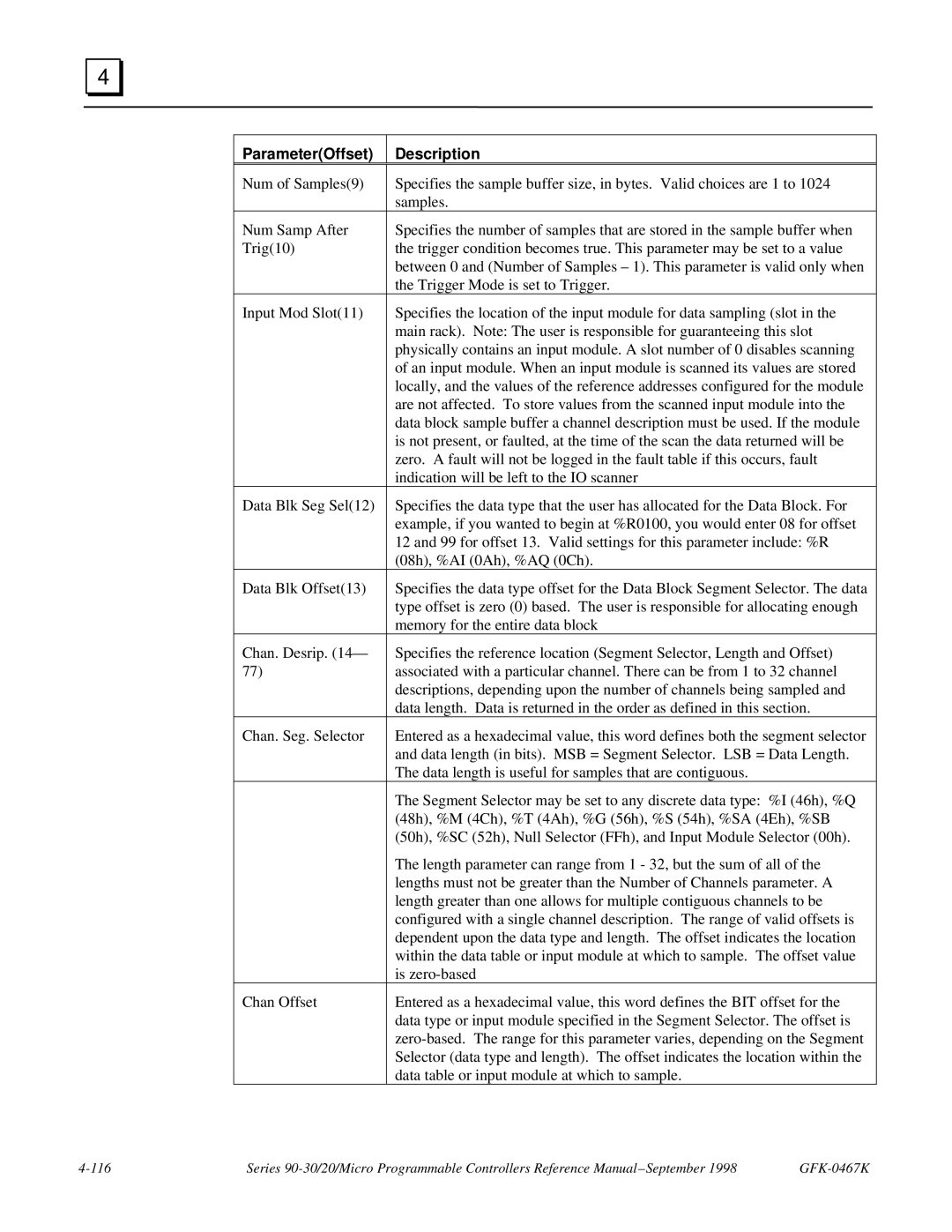
Parameter(Offset) | Description |
Num of Samples(9) | Specifies the sample buffer size, in bytes. Valid choices are 1 to 1024 |
| samples. |
Num Samp After | Specifies the number of samples that are stored in the sample buffer when |
Trig(10) | the trigger condition becomes true. This parameter may be set to a value |
| between 0 and (Number of Samples – 1). This parameter is valid only when |
| the Trigger Mode is set to Trigger. |
Input Mod Slot(11) | Specifies the location of the input module for data sampling (slot in the |
| main rack). Note: The user is responsible for guaranteeing this slot |
| physically contains an input module. A slot number of 0 disables scanning |
| of an input module. When an input module is scanned its values are stored |
| locally, and the values of the reference addresses configured for the module |
| are not affected. To store values from the scanned input module into the |
| data block sample buffer a channel description must be used. If the module |
| is not present, or faulted, at the time of the scan the data returned will be |
| zero. A fault will not be logged in the fault table if this occurs, fault |
| indication will be left to the IO scanner |
Data Blk Seg Sel(12) | Specifies the data type that the user has allocated for the Data Block. For |
| example, if you wanted to begin at %R0100, you would enter 08 for offset |
| 12 and 99 for offset 13. Valid settings for this parameter include: %R |
| (08h), %AI (0Ah), %AQ (0Ch). |
Data Blk Offset(13) | Specifies the data type offset for the Data Block Segment Selector. The data |
| type offset is zero (0) based. The user is responsible for allocating enough |
| memory for the entire data block |
Chan. Desrip. (14— | Specifies the reference location (Segment Selector, Length and Offset) |
77) | associated with a particular channel. There can be from 1 to 32 channel |
| descriptions, depending upon the number of channels being sampled and |
| data length. Data is returned in the order as defined in this section. |
Chan. Seg. Selector | Entered as a hexadecimal value, this word defines both the segment selector |
| and data length (in bits). MSB = Segment Selector. LSB = Data Length. |
| The data length is useful for samples that are contiguous. |
| The Segment Selector may be set to any discrete data type: %I (46h), %Q |
| (48h), %M (4Ch), %T (4Ah), %G (56h), %S (54h), %SA (4Eh), %SB |
| (50h), %SC (52h), Null Selector (FFh), and Input Module Selector (00h). |
| The length parameter can range from 1 - 32, but the sum of all of the |
| lengths must not be greater than the Number of Channels parameter. A |
| length greater than one allows for multiple contiguous channels to be |
| configured with a single channel description. The range of valid offsets is |
| dependent upon the data type and length. The offset indicates the location |
| within the data table or input module at which to sample. The offset value |
| is |
Chan Offset | Entered as a hexadecimal value, this word defines the BIT offset for the |
| data type or input module specified in the Segment Selector. The offset is |
| |
| Selector (data type and length). The offset indicates the location within the |
| data table or input module at which to sample. |
Series |