GE Fanuc Automation
Cimstar
Cimplicity
Promacro
Cimplicity 90-ADS
Preface
Related Publications
Preface
We Welcome Your Comments and Suggestions
Page
Contents
Contents
O Fault Table Explanations
Section Math Functions
Bit Operation Functions
Table Functions
Control Functions 107
137
Appendix a Instruction Timing
180
173
Table B-7
Introduction
Page
System Operation
Standard Program Sweep
PLC Sweep Summary
PLC Sweep
Calculate sweep time
Sweep Description Time Contribution ms Element
GCM
Sweep Time Calculation
Input Scan
Application Program Logic Scan or Solution
Output Scan
Programmer Communications Window
System Communications Window Models 331 and Higher
Programmer Communications Window Flow Chart
System Communications Window Flow Chart
PCM Communications with the PLC
PCM Communications with the PLC Models 331 and Higher
Standard Program Sweep Variations
Constant Sweep Time Mode
Page
YES
ON/RUN
OFF/STOP
Subroutine Blocks Series 90-30 PLC only
Program Organization and User References/Data
GFK-0467K System Operation
Examples of Using Subroutine Blocks
How Blocks Are Called
Type Description
User References
Retentiveness of Data
Transitions and Overrides
Page
Real
Data Types
Type Name Description Data Format
Byte
Reference Nickname Definition
System Status References
Reference Name Definition
Function Block Structure
Format of Program Function Blocks
MUL
Function Block Parameters
Power Flow In and Out of a Function
Power-Up
Power-Up and Power-Down Sequences
Power-Up Sequence
Flow Chart Terms
Power-Down
Time-of-Day Clock
Clocks and Timers
Elapsed Time Clock
Time-Tick Contacts
Watchdog Timer
Constant Sweep Timer
Privilege Level Description
Passwords
System Security
Type of Lock Description
Privilege Level Change Requests
Locking/Unlocking Subroutines
PLC I/O System
Series 90-30,90-20, and Micro I/O System
Catalog Pub Number Points Description
Model 30 I/O Modules
Input/Output Modules
Catalog Pub Number Description
Default Conditions for Model 30 Output Modules
Diagnostic Data
Data Formats
Catalog Number Description Points
Global Data
Model 20 I/O Modules
Micro PLCs
Section Title Description
Fault Explanation and Correction
Fault Class Examples
Fault Handling
Attribute Description
Fault Tables
Fault Summary
Fault Action Response by CPU
Fault Action
Fault Actions
Side Effect Description
Fault Reference Definitions
Accessing Additional Fault Information
Fault Description
PLC Fault Table Explanations
Loss of, or Missing, Option Module
Fault Actions
Daughterboard
Reset of, Addition of, or Extra, Option Module
System Configuration Mismatch
Program Block Checksum Failure
Low Battery Signal
Option Module Software Failure
Constant Sweep Time Exceeded
Application Fault
Informational
Corrupted User Program on Power-Up
Password Access Failure
No User Program Present
PLC CPU System Software Failure
Corrupted PLC Program Memory
Communications Failure During Store
Diagnostic
O Fault Table Explanations
Addition of I/O Module
Series 90-30/20/Micro Instructions Set
Function
Using Contacts
Type of Contact Display Contact Passes Power to Right
Relay Functions
Types of Coils
Using Coils
Type of Coil Display Power to Coil Result
Negated Coil
Normally Open Contact
Normally Closed Contact
Coil
Negative Transition Coil -↓
Retentive Coil -M
Negated Retentive Coil -/M
Positive Transition Coil -−
SET Coil -S
Reset Coil -R
Links
Retentive Reset Coil -RM
Retentive SET Coil -SM
Continuation Coils ---+ and Contacts +
Abbreviation Function
Timers and Counters
Function Block Data Required for Timers and Counters
15 14 13 12 11 10 9 5 4 3 2 1
Special Note on Certain Bit Operations
Ondtr
Parameter Flow Const None
Parameters
Valid Memory Types
Parameter Description
Const -PV
TMR
Parameters
Do DWL REL
Ofdt
EnableQ
Parameter flow %I %M %T %S %G %R AI %AQ const none
Upctr
Prtcnt
Dnctr
Countp
INT
Const
Abbreviation Function Description
Math Functions
INT
Standard Math Functions ADD, SUB, MUL, DIV
Data Type Description
I0001 Q0001
Function Operation Displays as
Math Functions and Data Types
Alwon
MOD INT, Dint
MOD
Sqrt INT, DINT, Real
I0001 Sqrt
Acos in =
Trig Functions SIN, COS, TAN, ASIN, ACOS, Atan
Enable
Logarithmic/Exponential Functions LOG, LN, EXP, Expt
Expt
Radian Conversion RAD, DEG
RAD
Relational Functions
Function Description
Expanded Description
BINFUL-I2
Word
Range INT, DINT, Word
Parameters
Constant
Range Truth Table Enable State L1 Value L2 Value
Bit Operation Functions
ROL
XOR
SHL
SHR
Or Word
WORD1 WORD2 Result
XOR Word
WORD3
Not Word
CAT -I1 Q-TAC
SHL and SHR Word
LEN
Length -N
ROL and ROR Word
R0001
Btst Word
PICKBIT-BIT
Bset and Bclr Word
SET
POS
Bpos Word
POS Word
If a Miscompare is Found
Mskcmp WORD, Dword
If All Bits in I1 and I2 are the Same
User logic to determine if a miscompare has occurred
I2 %M0017 = %M0033
I2 %M0017 = 606Fh = %M0033 = 000Fh =
Shfr
Data Move Functions
Move
Blkclr
Move BIT, INT, WORD, Real
Parameters
Before using the Move function
Constant value -IN1 Q- output parameter Q
Blkmov INT, WORD, Real
Enable IN1 IN7
Blkclr Word
BLK
Shfr BIT, Word
Parameters
Nxtcyc
Memory Required for a Bit Sequencer
Bitseq BIT
Step
DIR
Nxtseq
Commreq
Command Block
Sysid
Command block has the following structure
REQ
Table Functions
Arraymove INT, DINT, BIT, BYTE, Word
SNX
Const -SNX
00020
Input index -NX NX- output index
Contains the object of the search
I0001 Srch
Conversion Functions
BCD-4 INT
I0017-IN Q-%Q0033
INT BCD-4, Real
Total
Dint Real
R0017-IN Q-%R0001
Real INT, DINT, BCD-4, Word
Alwon INT Real
Word Real
I0002 REAL----------------RANGE
Trun INT, Dint
Real
Control Functions
Call
Doio
END
Input Example
Output Example
Normal Doio Enhanced Doio Module Execution Time
Enhanced do I/O Function for 331 and Later CPUs
SER
Enable Control Block
ParameterOffset Description
ParameterOffset Description
State Description
Status Extra Data
Offset Parameter Description
SER Data Block
SER Notes
GFK-0467K Series 90-30/20/Micro Instructions Set 119
Offset Register Parameter Description Value dec Value hex
GFK-0467K Series 90-30/20/Micro Instructions Set 121
Data Block
Channel Number Channel Contents
END
MCR
Differences Between MCRs and JUMPs
First + Endmcr
Endmcr
Jump
Non-nested Jump Nested Jump
Example of a nested Label
Label
Comment
Svcreq
Service Request Functions
GFK-0467K Series 90-30/20/Micro Instructions Set 133
∙ Disable Constant Sweep mode
Svcreq #1 Change/Read Constant Sweep Timer
Disable Constant Sweep mode Enable Constant Sweep mode
Ovswp
Svcreq #2 Read Window Values
Mode Name Value Description
Q0102
GFK-0467K Series 90-30/20/Micro Instructions Set 139
INT REQ Const -IN
High Byte Low Byte
Svcreq #4 Change System Comm. Window Mode and Timer Value
Word REQ
To Set a New Word Count
Svcreq #6 Change/Read Number of Words to Checksum
To Read the Current Word Count
Word INT
Svcreq #7 Change/Read Time-of-Day Clock
Const -+FNC
To Change/Read Date and Time Using BCD Format
Parameter Block Contents
Page
Svcreq #8 Reset Watchdog Timer
Svcreq #9 Read Sweep Time from Beginning of Sweep
Svcreq #10 Read Folder Name
Svcreq #11 Read PLC ID
Svcreq #12 Read PLC Run State
Svcreq #13 Shut Down Stop PLC
Svcreq #14 Clear Fault Tables
Fault Table Output Format
Svcreq #15 Read Last-Logged Fault Table Entry
PLC Fault Table Output Format
GFK-0467K Series 90-30/20/Micro Instructions Set 157
R0600
GFK-0467K Series 90-30/20/Micro Instructions Set 159
Svcreq #16 Read Elapsed Time Clock
Svcreq #18 Read I/O Override Status
Svcreq #23 Read Master Checksum
Svcreq #26/30 Interrogate I/O
Svcreq #29 Read Elapsed Power Down Time
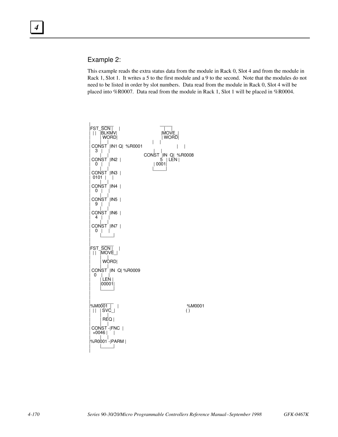
Read Extra Status Data Function #1
Svcreq #46Fast Backplane Status Access
Location Field Meaning
Write Data Function #2
Read/Write Data Function #3
GFK-0467K Series 90-30/20/Micro Instructions Set 169
Word Const -IN
IND
PID
Parameters. Uses 40 %R words that cannot be shared
PLC
PID Parameter Block
PID Parameters Overview
Register Parameter Low Bit Units Range of Values
PID Parameters Overview
Operation of the PID Instruction
Data Item Description
PID Parameters Details
Bit
Internal Parameters in RefArray
PID Algorithm Selection Pidisa or Pidind and Gains
Independent Term Algorithm Pidind
CV Amplitude and Rate Limits
PVs/CVs = Gs = K * e **-Tp s/1 + Tc s
Determining the Process Characteristics
Sample Period and PID Block Scheduling
Setting User Parameters Including Tuning Loop Gains
Setting Loop Gains Ziegler and Nichols Tuning Approach
Sample PID Call
GFK-0467K Series 90-30/20/Micro Instructions Set 185
Execution Time Description
Instruction Timing
340/41 311
Table A-1. Instruction Timing
GFK-0467K Appendix a Instruction Timing
331 340/41
Function Enabled Disabled Increment
Group Function
Disabled
Table A-1 InstructionTiming
End Instruction Service Request #7 Read #7 Set #14
Table A-3. Boolean Execution Speeds
Boolean Execution Speed
Instruction Sizes for 350 and 360 Series CPUs
Table A-2. Instruction Sizes for 350 and 360 Series CPUs
Interpreting Fault Tables
PLC Fault Table
Slot
Long/Short Indicator
Spare
Rack
Table B-1. PLC Fault Groups
PLC Fault Group
Table B-3. Alarm Error Codes for PLC CPU Software Faults
Fault Action
Error Code
Table B-2. PLC Fault Actions
Prgsyntaxerr
Table B-4. Alarm Error Codes for PLC Faults
Comreq
Plciscppcoverflow
Table B-6. PLC Fault Time Stamp
Fault Extra Data
PLC Fault Time Stamp
Table B-5. PLC Fault Data Illegal Boolean Opcode Detected
Fault Table
Table B-8. I/O Reference Address
Fault Address
Table B-7. I/O Fault Table Format Indicator Byte
Reference Address
Point
Fault Group
Table B-10. I/O Fault Groups
Table B-11. I/O Fault Actions
Fault Specific Data
Symbolic Fault Specific Data
Fault Actions for Specific Faults
Table B-13. I/O Fault Time Stamp
Fault Time Stamp
Instruction Mnemonics
Function Instruction Mnemonic Group
GFK-0467K Appendix C Instruction Mnemonics
Key Sequence Description
Page
Print side 1 of GFJ-055C on this
Print side 2 of GFJ-055C on this
Entered Displayed Description
Floating-Point Numbers
Page
Internal Format of Floating-Point Numbers
Exponent e Mantissa f Value of Floating Point Number
Values of Floating-Point Numbers
Invalid Entry Explanation
Entering and Displaying Floating-Point Numbers
Entered Displayed
Realindef
Errors in Floating-Point Numbers and Operations
Posinf
Neginf
General Case of Power Flow for Floating-Point Operations
Operation Input Output Powerflow
Editlock
Index
Commreq
Index
EXP Exponential functions
Greater than function Greater than or equal function
Not equal function
Real
Signed integer
Arraymove
Sweep time calculation Sweep, PLC
Viewlock