Chapter 8: Diagnostics/Maintenance
13.Place your fingers under the DS1 board and press firmly with your thumbs directly over the three connec- tors until the connectors are fully mated as shown.
Figure 8-5 Connectors flush and screws re-installed
14.With the DSP card fully mated, turn the assembly over and insert the four screws in the holes of the DS1 card matching the standoff spacers of the newly installed DSP card. Turn the screws clockwise with the #1 Phillips screwdriver until snug. DO NOT FULLY TIGHTEN IN THIS POSITION.
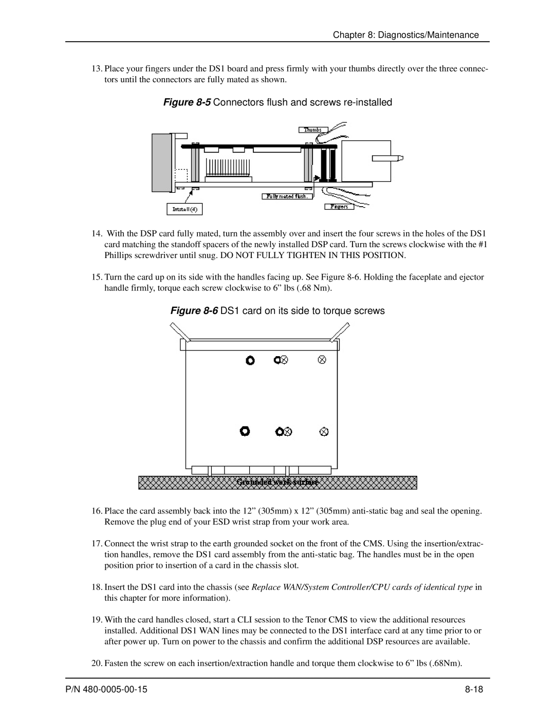
15.Turn the card up on its side with the handles facing up. See Figure
Figure 8-6 DS1 card on its side to torque screws
16.Place the card assembly back into the 12” (305mm) x 12” (305mm)
17.Connect the wrist strap to the earth grounded socket on the front of the CMS. Using the insertion/extrac- tion handles, remove the DS1 card assembly from the
18.Insert the DS1 card into the chassis (see Replace WAN/System Controller/CPU cards of identical type in this chapter for more information).
19.With the card handles closed, start a CLI session to the Tenor CMS to view the additional resources installed. Additional DS1 WAN lines may be connected to the DS1 interface card at any time prior to or after power up. Turn on power to the chassis and confirm the additional DSP resources are available.
20.Fasten the screw on each insertion/extraction handle and torque them clockwise to 6” lbs (.68Nm).
P/N |