Tenor Carrier MultiPath Switch CMS
Table of Contents
Hardware Components
Hardware Description
Front View
Installation
Getting Started with Command Line Interface CLI
ESD Antistatic Wrist Strap
Working with Snmp
System Alarms
Diagnostics/Maintenance
Call Detail Recording
Reset System
About this Guide
About this Guide
What’s included?
Preface-3
Product Guide Conventions
Finding Help
Overview
Overview
What is Tenor CMS?
Unique Design
Features
State-of-the-Art Configuration and Network Management
SelectNet Technology Safety Net
Multiple Channels/Signaling Supported
Dynamic Call Routing
Fractional T1/E1 Support
Gatekeeper Call Control Management
PacketSaver
IVR/RADIUS support
Easy Connect to Console
Powerful System Monitoring
Line Circuit Originated Calls
Capabilities
Intra-trunk Routing Hairpinning
Trunk Circuit Originated Calls
Data Network Calls
Other Call Routing Options
Virtual Tie Line
Snmp Support
Hop-off PBX Call
Call Registration
Gatekeeper Services
Gatekeeper
Zone Management
Configuration
Call Services
Overview
Hardware Components
Release Board Type P1.4.x P1.3.x P1.5.x P2.4.x P2.5.x
Hardware Description
Board interoperability
1Board supported according to CMS Release
Chassis CMS 14 Slot
Front with AC power
Power Inlet
Rear with AC power
Chassis LEDs
Front with DC Power
Card Slots Air Exhaust
Rear with DC power
Power Receptacle
Power Plug
Wrist Strap Ground Socket
Chassis CMS960 8 Slot
Strain Relief Mount
6Tenor CMS960 Rear View AC unit
7Tenor CMS960 Front View DC unit
Power Supplies Wrist Strap Ground Socket
8Tenor CMS960 Rear View DC unit
Front View with AC power
Chassis- CMS240 2 slot
Card Slots
Strain Relief Mount Fuse
Rear View with AC power
Card Slots
Front view with DC power
12Tenor CMS Rear View DC unit
Rear View with DC power
13System Controller Card
System Controller Card Available for CMS P1.5.x
Pin # Signal Definition Color
15DB-9 Female Connector Pin Order
CPU Card Available for CMS P2.x.x
16CPU Card Front
Front View
17CPU Card Rear
Rear View
4Input/Output 10/100 Ethernet port
19DB-9 Female Connector Pin Order
DS1 WAN Card with DSP module
WAN Cards
Status LEDs
Hot Swap LED
Port# Pin Signal Definition
21RJ-48 Port Pin Order DS1 Signal for DS1Card RJ-48 Ports
22 T1 WAN Card
T1 WAN Card
Hardware Components
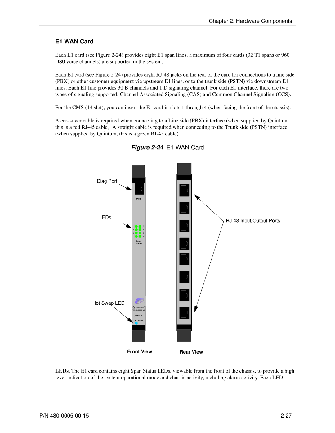
24 E1 WAN Card
E1 WAN Card
Hardware Components
9Usage Guidelines WAN Card Usage Required DSP Cards
DSP Resource Card
Hardware Components
Cable Usage
Cables
10Cables Supported
RJ-45 Cables
11RJ-45 10/100BT Connector Pinouts
RJ-45 Ethernet Cable 10/100
Pin # Connects to
12RJ-48 Connector Pinouts for T1/E1/DS
RJ-48 Cables
RJ-48 to RJ-48 Straight Cable T1/E1/DS1 WAN to Trunk Side
13RJ-48 Connector Pinouts for T1/E1/DS1
Pin # Signal Definition Color for Connector
RJ-48 to RJ-48 Crossover Cable T1/E1/DS1 WAN to Line Side
DB-9 to DB-9 Null Modem Cable for System Controller card
14DB-9 Connector Pinouts Pin # Function Description
DB-9 Serial RS-232 Cable for CPU card
15DB-9 Connector Pinouts Pin # Function Description
CMS 14 slot
Power Supplies
With AC Power
With DC Power
CMS960 8 slot
CMS240 2 slot
40CMS240 AC Power Supplies
Installation
Install in Rack
Installation
Pre-Installation Guidelines
Inspect Package Contents
Installation
1Rack Installation
Connection
Introduction
Connect to Trunk Interface Pstn
3Connect to Line Interface
Connect to Line Interface PBX
Connect to Ethernet LAN with System Controller Card
4Connect to Ethernet Hub/Switch
Connect to Ethernet LAN with CPU Card
5Connect to Ethernet Hub/Switch
6Connect to PC Com
Connect to PC Console with System Controller
7Connect to PC Com
Connect to PC Console with CPU
Material Requirements
Connect Power CMS 14 slot, DC only
Power Requirements
Connect Power
48 RTN
Installation
Connect Power CMS960 8 slot and CMS240 2 slot, DC only
Power Inlet
Chassis Rear Circuit Breaker
14Strip away wire
Rivet
Install Power Cord Strain Relief AC only
Power up the System for AC unit
Prevent Electrostatic Discharge Damage
ESD Antistatic Wrist Strap
Provide Grounding
Assign IP Address
18Port Settings Window
Installation
Upgrade from Disk
Install Software Upgrade via CMS Software Update Utility
20Main Backup Screen
Backup
Upgrade via Network
Restore previous versions
22Main Backup Screen
Getting Started with Command Line Interface CLI
Modes
What is the Command Line Interface?
Getting Started with Command Line Interface CLI
Options
User Login IDs
Getting Started with Command Line Interface
Navigation
CLI Menu Tree Basic View
CLI Menu Tree
CLI Menu Tree Expanded View
RadiusInfo-RoutingServer
EthernetInterface for slot CASSignalingGroup
CodecProfile-1
RadiusInfo- UserServer
LineCircuitRoutingGroup
ISDNSignalingGroup
H323 SignalingGroup
Cont
GateKeeperParam
VoIPNetwork DoMain ZoNe GateWay FaxProfile
IPRoutingGroup
ToneProfile
For Windows 95/Windows
Access CLI
Telnet Connection
Serial Port Connection
Getting Started with Command Line Interface CLI
Move within modes
Move around within CLI
Move between modes
To reach Enter
Example
Execute commands
Mode-specific commands
Global commands
Surf
Clear
Configuration Mode
Menu-specific commands
Set
Example
Add
Delete
Discard
Reset
Maintenance mode
Alarm
Monitor mode
Event Log
Diagnostic Mode
Clock Source
Configure Common CLI Options
Gateway
Channel Group
Digital Interface
Trunk Group
Switch Protocol
Working with Snmp
What is SNMP?
How does Tenor CMS utilize SNMP?
Working with Snmp
Installation Requirements
Download and install Snmp Related Files
These lines are added to the file HPOVRoot\conf\oidtosym
1Tenor Snmp Agent Icon
Configure network manager IP address
Click Connect Remote System
Working with Snmp
View Alarm Status via Tenor CMS icon
Launching Command Line Interface CLI from HP Openview
Launch Command Line Interface with pop-up menu as follows
Set up Tenor CMS status polling
Set up Debug Message Display window
Launch CLI by double-clicking as follows
Call Detail Recording
Call Detail Recording
Overview
1Flow of CDR Information
Establish connection between Tenor CMS and CDR Server
Configure Tenor CMS for connection to CDR server
Setup CDR Server and assign password
Change CDR Password if required
CDR Server Establishes Connection with Tenor CMS
Tenor CMS Establishes Connection with CDR Server
Sample Record for Standard and Extended CDR Format 0, 1, 100
CDR Output
Cause Code Definitions
Call Detail Recording
Sample Record for Extended CMS CDR Format 3, 4, 103
Record 1 Sample includes fields for formats 3
Incoming/Outgoing IP DN
Cause Code Definitions
Call Detail Recording
System Alarms
System Alarms
Monitor Alarms
How to Read Alarms
1Alarm Fields and Definitions Valid Entry
Field Definition Valid Entry
Valid Alarms
2List of Valid Alarms
Severity Alarm Description
Severity Alarm Description
Severity Alarm Description
Severity Alarm Description
View Alarms
Display all Alarms
Display Active Alarms
3Alarm History Sample
Display Alarm History
Diagnostics/Maintenance
Before you Begin
Diagnostics/Maintenance
Common Symptoms/Problems
Diagnostics
Verify use of null modem cable for System Controller
Common Symptom/Problem Description/Solution
Unit Provisioning
Ping Unit
Inspect and Replace Fuse for AC power only
DSP Card
Monitoring
Faceplate LEDs
Inspect Backplane/Chassis
T1 WAN
DS1 Card
CPU Card Front
System Controller Card
CPU Card Rear
Power Supply CMS, 14 slot
Power Supply CMS240 and CMS960
Alarms
Component Status
General Maintenance
Clean/Replace Foam Air Filter for CMS, 14 slot only
Replace System Fan for CMS, 14 slot only
Change Password
Reset System
Card Rear Transition
Card Maintenance/Replacement
2Cards/Slot Installation Guidelines
Slot Installation Special Instructions Label
T1 WAN
Replace WAN/System Controller/CPU cards of identical type
1WAN Interface Board Handles
2Remove four screws from exposed end
Replace/Change DSP Module on DS1 card
3DS1 card with heat sink facing up
5Connectors flush and screws re-installed
Move card location or change card type
Quintum Technologies, Inc
If you need Additional Help
Page
How does CMS fit in the VoIP Network?
Common Network Types Intranet
Extranet
Internet
Enterprise Network
Typical CMS Applications
Figure A-1Service Provider Network
Service Provider Network
Figure A-2Calling Card Application
Calling Card Application
Figure A-3 OPX Example
Off Premises Exchange OPX
Appendix B Specifications/Approvals
Appendix B Specifications/Approvals
Voice/Fax
Line Side PBX / Trunk Side Pstn Connections
Environmental
LAN Connection
Physical
Electrical
Storage Temperature 14 to 140 F, -10 to 60C
Tenor CMS 8-port T1 WAN Card
Agency Approvals
System Controller Application Card
CPU Card
Tenor CMS Power Supply
Tenor CMS 120-port DSP Application Card
Tenor CMS 8-port DS1 WAN Card
FCC Warnings
Appendix B Specifications/Approvals
Glossary-9
Glossary
Glossary-10
Glossary-11
480-0005-00-15 Index-1
Index
480-0005-00-15 Index-2
FCC
480-0005-00-15 Index-3
Hot swap 2-20,2-26,2-28,8-8LEDs 2-25,8-7
480-0005-00-15 Index-4
Quintum RMA Procedure
Warranty
Please Note All shipments require an authorized RMA number
Quintum TECHNOLOGIES, INC Documentation Notice