SmartConnect User’s Guide
External Trunks
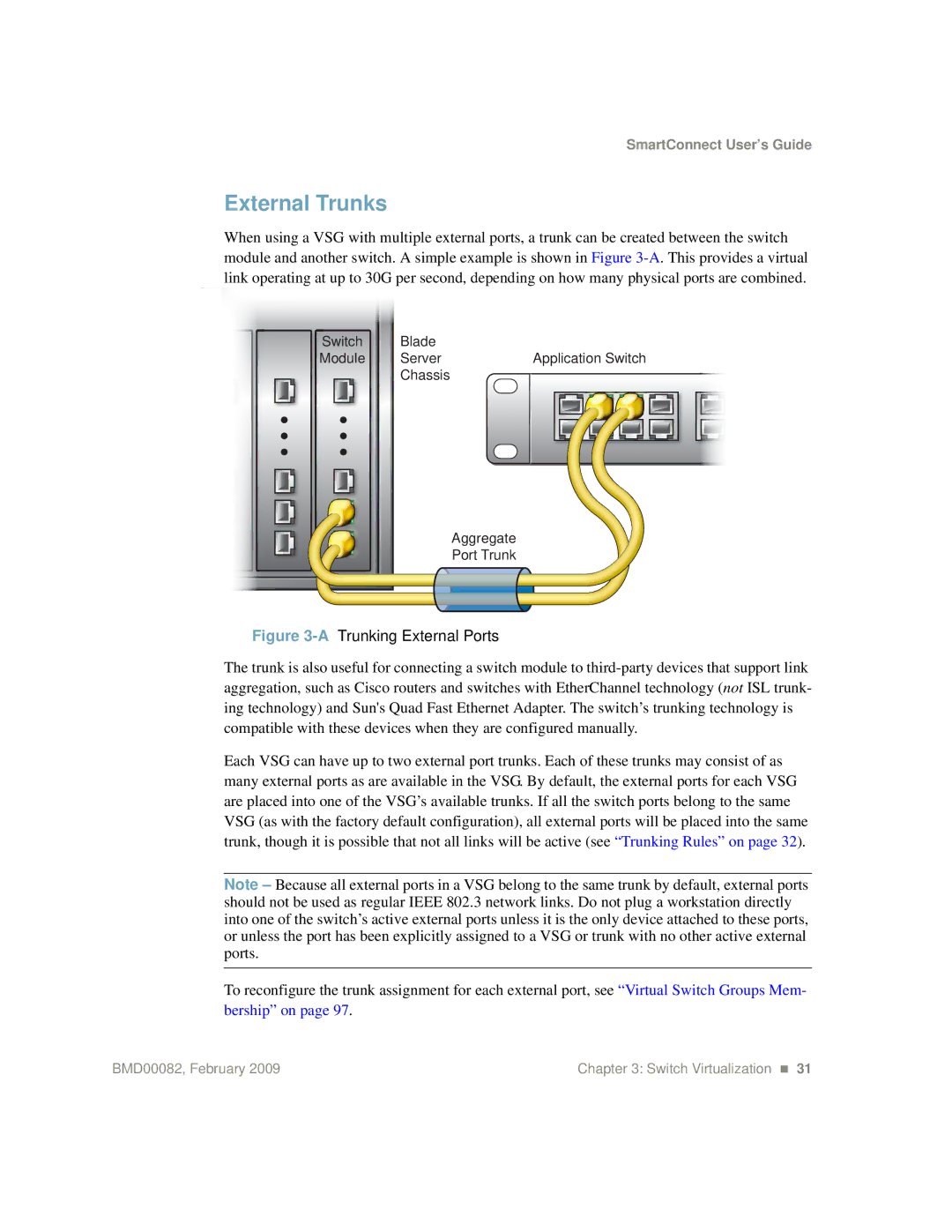
When using a VSG with multiple external ports, a trunk can be created between the switch module and another switch. A simple example is shown in Figure
Switch | Blade | Application Switch | |||||||||||||
Module | Server | ||||||||||||||
|
| Chassis |
|
|
|
|
|
|
|
|
|
|
|
|
|
|
|
|
|
|
|
|
|
|
|
|
|
|
|
| |
|
|
|
|
|
|
|
|
|
|
|
|
|
|
|
|
|
|
|
|
|
|
|
|
|
|
|
|
|
|
|
|
Aggregate
Port Trunk
Figure 3-A Trunking External Ports
The trunk is also useful for connecting a switch module to
Each VSG can have up to two external port trunks. Each of these trunks may consist of as many external ports as are available in the VSG. By default, the external ports for each VSG are placed into one of the VSG’s available trunks. If all the switch ports belong to the same VSG (as with the factory default configuration), all external ports will be placed into the same trunk, though it is possible that not all links will be active (see “Trunking Rules” on page 32).
Note – Because all external ports in a VSG belong to the same trunk by default, external ports should not be used as regular IEEE 802.3 network links. Do not plug a workstation directly into one of the switch’s active external ports unless it is the only device attached to these ports, or unless the port has been explicitly assigned to a VSG or trunk with no other active external ports.
To reconfigure the trunk assignment for each external port, see “Virtual Switch Groups Mem- bership” on page 97.
BMD00082, February 2009 | Chapter 3: Switch Virtualization 31 |