SmartConnect User’s Guide
Switch failover is disabled by default, but can be enabled for any VSG. When enabled, switch failover works as follows:
If some (or all) of the links fail in the failover trigger, the switch disables all internal ports in the VSG. This causes the NIC team on the affected server blades to failover from the primary to the backup NIC. This process is called a failover event.
When the appropriate number of links return to service, the switch enables the internal ports in the VSG. This causes the NIC team on the affected server blades to fail back to the primary switch (unless
Setting the Number of Links to Trigger Failover
The Number of Links to Trigger Failover specifies the minimum number of operational links in the VSG that triggers a failover event. For example, if the limit is four, a failover event occurs when the number of operational links in the trigger is four or fewer. If the trigger num- ber is set to zero (0), the switch triggers a failover event only when no links in the VSG are operational.
Configuring Switch Failover
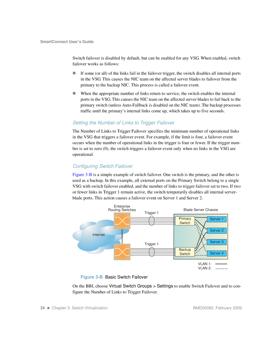
Figure 3-B is a simple example of switch failover. One switch is the primary, and the other is used as a backup. In this example, all external ports on the Primary Switch belong to a single VSG with switch failover enabled, and the number of links to trigger failover set to two. If two or fewer links in Trigger 1 remain active, the switch temporarily disables all internal server- blade ports. This action causes a failover event on Server 1 and Server 2.
Enterprise
Routing Switches
Internet
Trigger 1
Trigger 1
Blade Server Chassis
Primary | Server 1 |
Switch |
|
| Server 2 |
| Server 3 |
Backup | Server 4 |
Switch |
VLAN 1:
VLAN 2:
Figure 3-B Basic Switch Failover
On the BBI, choose Virtual Switch Groups > Settings to enable Switch Failover and to con- figure the Number of Links to Trigger Failover.
34 Chapter 3: Switch Virtualization | BMD00082, February 2009 |
