The 8 pins of the RJ45 connector can be configured to match either of two
NOTE: By default, as configured in the factory, the SCB2 baseboard will have the rear RJ45 serial port configured to support a DSR signal.
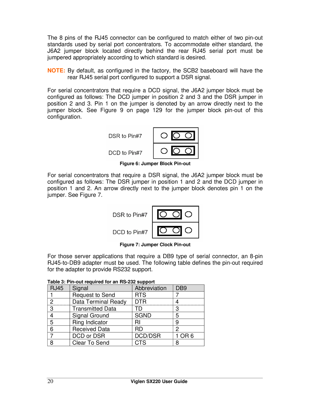
For serial concentrators that require a DCD signal, the J6A2 jumper block must be configured as follows: The DCD jumper in position 2 and 3 and the DSR jumper in position 2 and 3. Pin 1 on the jumper is denoted by an arrow directly next to the jumper block. See Figure 9 on page 129 for the jumper block
Figure 6: Jumper Block Pin-out
For serial concentrators that require a DSR signal, the J6A2 jumper block must be configured as follows: The DSR jumper in position 1 and 2 and the DCD jumper in position 1 and 2. An arrow directly next to the jumper block denotes pin 1 on the jumper. See Figure 7.
Figure 7: Jumper Clock Pin-out
For those server applications that require a DB9 type of serial connector, an
Table 3:
RJ45 | Signal | Abbreviation | DB9 |
1 | Request to Send | RTS | 7 |
2 | Data Terminal Ready | DTR | 4 |
3 | Transmitted Data | TD | 3 |
4 | Signal Ground | SGND | 5 |
5 | Ring Indicator | RI | 9 |
6 | Received Data | RD | 2 |
7 | DCD or DSR | DCD/DSR | 1 OR 6 |
8 | Clear To Send | CTS | 8 |
20 | Viglen SX220 User Guide |