Hardware Guide For J-series Services Routers
Junos Software with Enhanced Services Hardware Guide
End User License Agreement
Iii
Page
Abbreviated Table of Contents
Junos Software with Enhanced Services Hardware Guide
Table of Contents
Chapter PIM Overview
Viii Table of Contents
Chapter Preparing for Router Installation
Part Installing a Services Router
Part Maintaining Services Router Hardware
115
119
169
157
197
Part Series Requirements and Specifications
Xii Table of Contents
179
Index
Part
Page
Objectives
About This Guide
Objectives
Audience
How to Use This Manual
Supported Routing Platforms
Tasks and Related Documentation
How to Use This Manual
About This Guide
Task Related Documentation
Text and Syntax Conventions
Document Conventions
Plain text like this
Stub default-metric metric Broadcast multicast
Convention Description
Edit Root@# set system domain-name
All Platforms
Convention Description Examples
Documentation Feedback
Book Description
Documentation Feedback
Xxii Requesting Technical Support
Requesting Technical Support
About This Guide Requesting Technical Support
Page
Services Router Overview
Services Router Overview
Page
Overview of Services Routers
J2320 Services Router Overview
J2320 Services Router Overview
J2350 Services Router Overview
J2350 Services Router Overview
J4350 Services Router Overview
Overview of Services Routers
J4350 Services Router Overview
J6350 Services Router Overview
J6350 Services Router Overview
Series Services Router Hardware Features
J2320 and J2350 Services Router Hardware Features
J2320 and J2350 Services Router Hardware Features
Front of J2320 Chassis
J2320 and J2350 Chassis
Rear of J2320 Chassis
Front of J2350 Chassis
J2320 Hardware Components
Rear of J2350 DC-Powered Chassis
Description Value
J2320 and J2350 Physical Specifications
J2320 and J2350 Routing Engine Hardware
J2320 and J2350 Boot Devices
12 J2320 and J2350 Services Router Hardware Features
J2320 and J2350 Midplane
J2320 and J2350 Front Panel
Physical Interface Modules PIMs
Power Button and Power LED
J2320 and J2350 Power LED
14 J2320 and J2350 Services Router Hardware Features
J2320 and J2350 Status LED
J2320 and J2350 Alarm LED
Reset Config Button
16 J2320 and J2350 Services Router Hardware Features
J2320 and J2350 HA LED
USB Port
Built-In Gigabit Ethernet Ports
Console Port
AUX Port
J2320 and J2350 External Compact Flashes
J2320 Power System
J2350 Power System
18 J2320 and J2350 Services Router Hardware Features
J2320 and J2350 Cooling System
20 J4350 and J6350 Services Router Hardware Features
J4350 and J6350 Services Router Hardware Features
J4350 and J6350 Chassis
J4350 and J6350 Services Router Hardware Features
Front of J4350 and J6350 Chassis
Rear of J4350 AC-Powered Chassis
Rear of J4350 DC-Powered Chassis
24 J4350 and J6350 Services Router Hardware Features
J4350 and J6350 Physical Specifications
J4350 and J6350 Boot Devices
J4350 and J6350 Midplane
J4350 and J6350 Routing Engine Hardware
J4350 and J6350 Front Panel
26 J4350 and J6350 Services Router Hardware Features
Power LED
Slot Number Diagram on Front Panel
Alarm LED
28 J4350 and J6350 Services Router Hardware Features
Status LED
HA LED
30 J4350 and J6350 Services Router Hardware Features
J4350 Power System
J6350 Power System
Power Supply LED
State Description
J4350 and J6350 Cooling System
32 J4350 and J6350 Services Router Hardware Features
Airflow Through the J4350 and J6350 Chassis
Page
PIM Overview
PIM Terms
PIM Terms
Term Definition
PIM Terms
Dialer filter
PIM Overview
Field-Replaceable PIMs
J2320 and J2350 Field-Replaceable PIM and Module Summary
Field-Replaceable PIMs
J4350 and J6350 Field-Replaceable PIM Summary
Supported Software Releases
For This PIM Port Numbering
J4350 and J6350 Field-Replaceable PIM and Module Summary
Fe-1/0/0
Port, 6-Port, 8-Port, and 16-Port Gigabit Ethernet uPIMs
T3-0/0/0
E3-2/0/0
Port Gigabit Ethernet uPIM
PIM Overview
Optical Interface Support for SFP Gigabit Ethernet uPIMs
Port Gigabit Ethernet ePIMs
Copper Gigabit Ethernet ePIM
Optical Interface Support for SFP Gigabit Ethernet ePIM
Dual-Port Serial PIM
Dual-Port Serial PIM
Dual-Port T1 or E1 PIM
Status LEDs for Serial Ports
Color State Description
Status LEDs for T1 and E1 Ports
Dual-Port Channelized T1/E1/ISDN PRI PIM
Channelized T1/E1/ISDN PRI PIM
T3 or E3 PIM
LEDs for Channelized T1/E1/ISDN PRI PIMs
Label Color State Description
Status LEDs for T3 and E3 Ports
E3 PIM
LEDs for Dual-Port Fast Ethernet PIM
Dual-Port Fast Ethernet PIM
Port Fast Ethernet ePIM
Port Fast Ethernet ePIM
LEDs for 4-Port Fast Ethernet ePIM
Port Isdn BRI PIMs
Online
LEDs for Isdn BRI S/T and U PIMs
LEDs for Adsl PIMs
Adsl 2/2+ Annex a PIM
Shdsl PIM
LEDs for G.SHDSL PIMs
Page
Installing a Services Router
Installing a Services Router
Page
Preparing for Router Installation
General Site Guidelines
General Site Guidelines
Rack Requirements
Rack Size and Strength for J2320 and J2350 Routers
Rack Requirements
Preparing for Router Installation
Rack Size and Strength for J4350 and J6350 Routers
Connection to Building Structure
Router Environmental Tolerances
Fire Safety Requirements
Router Environmental Tolerances
Fire Suppression
Power Guidelines, Requirements, and Specifications
Power Guidelines, Requirements, and Specifications
Fire Suppression Equipment
Electromagnetic Compatibility
Site Electrical Wiring Guidelines
Signaling Limitations
Radio Frequency Interference
Router Power Requirements
AC Power, Connection, and Power Cord Specifications
Specification
Country Electrical Specifications Plug Standards
AC Power Cord Specifications
DC Power, Connection, and Power Cable Specifications
Planning for Power Management
Series PIM Power Consumption and Heat Dissipation
Network Cable Specifications
Maximum Power and Heat Capacities of J-series Models
Isdn Provisioning
Item or Task Performed By Date
Site Preparation Checklist
Site Preparation Checklist
Site Preparation Checklist
Page
Installing and Connecting a Services Router
Before You Begin
Before You Begin
Unpacking a J-series Services Router
Unpacking a J-series Services Router
Installing J2320 and J2350 Routers
Installing and Connecting a Services Router
Installing J2320 and J2350 Routers
Installing J4350 and J6350 Routers
Installing J4350 and J6350 Routers
Installing the Mounting Brackets
Attaching the Center Screw to the Rack
Connecting Interface Cables to Services Routers
Connecting Interface Cables to Services Routers
Chassis Grounding
Connecting Power
Connecting AC Power
Connecting Power
Connecting AC Power to the J2320 Services Router
Connecting AC Power to the J2350 Services Router
Connecting DC Power
VDC and RTN
Connecting DC Power to the J2350 Services Router
Powering a Services Router On and Off
Powering a Services Router On and Off
Page
Basic Connectivity Terms
Establishing Basic Connectivity
Basic Connectivity Terms
Basic Connectivity Terms
Basic Connectivity Overview
Root Password
Basic Connectivity Overview
Router Identification
Establishing Basic Connectivity
Network Settings
Default Gateway
Time Zone and System Time
Backup Router
Loopback Address
Built-In Ethernet Interface Address
Management Access
Connecting to a Services Router
Connecting to a Services Router
192.168.1.1
Connecting to the J-Web Interface
Connecting to the CLI Locally
COM1
Connecting to the Console Port on J2320 and J2350 Routers
Connecting to the CLI Remotely
Configuring the Modem at the Router End
Connecting to the CLI at the User End
Connecting the Modem to the Console Port
Configuring Basic Settings with J-Web Quick Configuration
Configuring Basic Settings with J-Web Quick Configuration
Field Function Your Action
Set Up Quick Configuration Summary
Ge-0/0/0 Address
Time
About the CLI Configuration Wizard
Basic Configuration Wizard Summary
Prompt Function Your Action
Enter host name
Yes, no no
Enter IP address for the name server
Enter a security zone name to associate this interface to
Would you like to configure default gateway? yes, no no
Enter IP address for the default gateway
Subnet mask bit length for this interface 1-32
Sample Settings on a Services Router
Configuring Basic Settings with a Configuration Editor
Configuring Basic Settings
Set ntp server
Task Web Configuration Editor
Set services ssh
Ssh-rsa
Verifying Basic Connectivity and the Configuration
Displaying Basic Connectivity Configurations
Displaying Basic Connectivity Configurations
Installing Junos Software with Enhanced Services
116
Maintaining Services Router Hardware
Maintaining Services Router Hardware
Page
Replacing Hardware Components
Tools and Parts Required
Tools and Parts Required
Tools and Parts Required
Replacing the Console Port Cable
Replacing a PIM
Removing a PIM
Replacing a PIM
Replacing Hardware Components
Installing a PIM
Installing a PIM
Replacing PIM Cables
Installing PIM Cables
Replacing PIM Cables
Removing PIM Cables
User@host request chassis fpc slot pim-slotonline
To replace the cover on the J2320 and J2350 chassis
Matching the Chassis Slots and Tabs
Location of J2320 and J2350 Internal Compact Flash
Removing the J2320 or J2350 Internal Compact Flash
Location of J4350 and J6350 Compact Flash
Junos Software with Enhanced Services Hardware Guide
Removing the J4350 or J6350 Compact Flash
Replacing External Compact Flashes
Replacing External Compact Flashes
Replace the compact flash slot cover
Replacing USB Storage Devices
Removing the USB Storage Device
Replacing USB Storage Devices
Installing the USB Storage Device
Replacing Dram Modules
Replacing Dram Modules
J4350 and J6350 Dram Location
Removing a Dram Module
Installing or Replacing Dram Modules
Installing a Dram Module
Replacing Power System Components
Replacing AC Power Supply Cords
Replacing Power System Components
Removing an AC Power Supply from J6350 Routers
Removing an AC Power Supply
Installing an AC Power Supply in J6350 Routers
Installing an AC Power Supply
Replacing DC Power Supply Cables
Removing a DC Power Supply
Removing a DC Power Supply
Installing a DC Power Supply
VDC and RTN
Installing a DC Power Supply
Removing a J2320 or J2350 Crypto Module
Removing a J2320 or J2350 Crypto Accelerator Module
Installing a J2320 or J2350 Crypto Accelerator Module
Installing a J2320 or J2350 Crypto Accelerator Module
User@host show chassis hardware
Removing a J4350 or J6350 Crypto Accelerator Module
Removing a J4350 or J6350 Crypto Module Screw
Installing a J4350 or J6350 Crypto Accelerator Module
Replacing Air Filters on J2350 Routers
Replacing Air Filters on J2350 Routers
Replacing Air Filters on J4350 and J6350 Routers
Replacing Air Filters on J4350 and J6350 Routers
Attaching Air Filter and Filter Cover
Page
Troubleshooting Hardware Components
Troubleshooting a Services Router
Troubleshooting Hardware Components
Monitoring and Correcting Chassis Alarm Conditions
Chassis Alarm Conditions and Corrective Actions
Component Alarm Conditions
Corrective Action Alarm Severity
Troubleshooting a Services Router
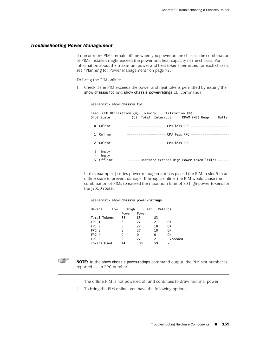
Troubleshooting Power Management
Using the Reset Config Button
Changing the Reset Config Button Behavior
Recovering the Root Password
Recovering the Root Password
Junos Software with Enhanced Services Hardware Guide
Ok boot -s
Recovering Primary Boot Devices
Recovering Primary Boot Devices
Why Compact Flash Recovery Might Be Necessary
Recommended Recovery Hardware and Software
Physdiskwrite utility
Configuring Internal Compact Flash Recovery
Recommended Recovery Hardware and Software
Recommended Hardware and Software Examples
\ physdiskwrite -u junos-jseries-7.0-20041028.0-export-cf512
Contacting the Juniper Networks Technical Assistance Center
Contacting the Juniper Networks Technical Assistance Center
Page
Contacting Customer Support and Returning Hardware
Locating Component Serial Numbers
Locating Component Serial Numbers
Location of the Serial Number ID Labels
J2320 and J2350 Chassis Serial Number and Agency Labels
Contacting Customer Support and Returning Hardware
J4350 and J6350 Chassis Serial Number and Agency Labels
Contacting Customer Support
Power Supply Serial Number Labels
Return Procedure
PIM Serial Number Label
Packing a Router or Component for Shipment
Tools and Parts Required
Packing a Router or Component for Shipment
Packing Components for Shipment
Packing the Services Router for Shipment
Contacting Customer Support and Returning Hardware
Page
Series Requirements and Specifications
Series Requirements and Specifications
Page
Serial PIM Cable Specifications
Network Cable Specifications and Connector Pinouts
Serial PIM Cable Specifications
Port Serial PIM Cables and Connectors
LFH-60 Pin DB-25 Pin LFH-60 Pairing Description
RS-232 DTE Cable Pinout
RS-232 DTE Cable Pinout
RS-422/449 EIA-449 DTE Cable Pinout
RS-232 DCE Cable Pinout
RS-422/449 EIA-449 DTE Cable Pinout
RS-232 DCE Cable Pinout
Receive Data a
RS-422/449 EIA-449 DCE Cable Pinout
RS-422/449 EIA-449 DCE Cable Pinout
EIA-530A DTE Cable Pinout
EIA-530A DTE Cable Pinout
EIA-530A DCE Cable Pinout
EIA-530A DCE Cable Pinout
LFH-60 Pin 34 Pin LFH-60 Pairing Description
DTE Cable Pinout
35 DTE Cable Pinout
21 DTE Cable Pinout
LFH-60 Pin DB-15 Pin LFH-60 Pairing Description
DCE Cable Pinout
35 DCE Cable Pinout
21 DCE Cable Pinout
Gigabit Ethernet uPIM RJ-45 Connector Pinout
Fast Ethernet RJ-45 Connector Pinout
Gigabit Ethernet uPIM RJ-45 Connector Pinout
Fast Ethernet RJ-45 Connector Pinout
Gigabit Ethernet ePIM RJ-45 Connector Pinout
Gigabit Ethernet ePIM RJ-45 Connector Pinout
Gigabit Ethernet ePIM RJ-45 Connector Pinouts
Pin Signal Name
RJ-45 Chassis Console Connector Pinout
DB-9 Console Connector Pinout
E1 and T1 RJ-48 Cable Pinouts
RJ-48 Connector to RJ-48 Connector Straight Pinout
RJ-48 Connector to RJ-48 Connector Crossover Pinout
192 E1 and T1 RJ-48 Cable Pinouts
RJ-48 Connector to DB-15 Connector Crossover Pinout
RJ-48 Connector to DB-15 Connector Straight Pinout
PinSignal
E3 and T3 BNC Connector Pinout
Adsl and G.SHDSL RJ-11 Connector Pinout
Adsl and G.SHDSL RJ-11 Connector Pinout
Isdn RJ-45 Connector Pinout
Isdn RJ-45 Connector Pinout
Isdn RJ-45 Connector Pinout
Page
Safety and Regulatory Compliance Information
Definition of Safety Warning Levels
Definition of Safety Warning Levels
Page
Safety Guidelines and Warnings
Safety Guidelines and Warnings
General Safety Guidelines and Warnings
Safety and Regulatory Compliance Information
Qualified Personnel Warning
Preventing Electrostatic Discharge Damage
Electrical Safety Guidelines and Warnings
General Electrical Safety Guidelines
AC Power Electrical Safety Guidelines
DC Power Electrical Safety Guidelines
DC Power Disconnection Warning
Power Sources for Redundant Power Supplies
DC Power Grounding Requirements and Warning
Varten 48 V, +RTN varten +RTN, maajohto maajohtoon
DC Power Wiring Sequence Warning
Page
DC Power Wiring Terminations Warning
Grounded Equipment Warning
Case of Electrical Accident
Multiple Power Supplies Disconnection Warning
Page
Power Disconnection Warning
TN Power Warning
Telecommunication Line Cord Warning
Installation Safety Guidelines and Warnings
Installation Instructions Warning
Chassis Lifting Guidelines
Rack-Mounting Requirements and Warnings
Junos Software with Enhanced Services Hardware Guide
Safety and Regulatory Compliance Information
Junos Software with Enhanced Services Hardware Guide
Ramp Warning
Laser and LED Safety Guidelines and Warnings
General Laser Safety Guidelines
Class 1 Laser Product Warning
Class 1 LED Product Warning
Laser Beam Warning
Radiation from Open Port Apertures Warning
Maintenance and Operational Safety Guidelines and Warnings
Battery Handling Warning
Jewelry Removal Warning
Lightning Activity Warning
Operating Temperature Warning
Junos Software with Enhanced Services Hardware Guide
Product Disposal Warning
Agency Approvals
Agency Approvals
Canada
Lithium Battery
Compliance Statements for Environmental Requirements
Compliance Statements for EMC Requirements
Compliance Statements for EMC Requirements
European Community
Japan
United States
FCC Part 15 Statement
FCC Part 68 Statement
Junos Software with Enhanced Services Hardware Guide
Index
Index
Junos Software with Enhanced Services Hardware Guide Index
Symbols
Basic connectivity
See also LEDs
DC power Cables See DC power cables Connecting power
Eprom
Grounding Cable
Web interface
PIM
Crypto Accelerator Module 146
AUX
Power supplies, J6350
Defining cli wizard 107
SSH
TX/RX LED
Rotating fans, compact flash Replacement 127
Junos Software with Enhanced Services Hardware Guide Index