HD CAMERA RECORDER
GY-HD200U/CHU INSTRUCTIONS GY-HD200E/CHE GY-HD201E/CHE
E
INTRODUCTION
CONTROLS, INDICATORS AND CONNECTORS
PREPARATIONS
PREPARATIONS FOR OPERATION
SETTING AND
ADJUSTMENTS BEFORE SHOOTING
SHOOTING
OPERATION
PLAYBACK MODE
USING EXTERNAL COMPONENTS
MENU SCREENS
FEATURES OF THE CAMERA SECTION
OTHERS
© 2006 Victor Company of Japan, Limited |
Thank you for purchasing this JVC product. Before operating this device, please read the instructions carefully to ensure the best possible performance.
For Customer Use:
Enter below the Serial No. which is located on the body. Retain this information for future reference.
Model No.
Serial No.
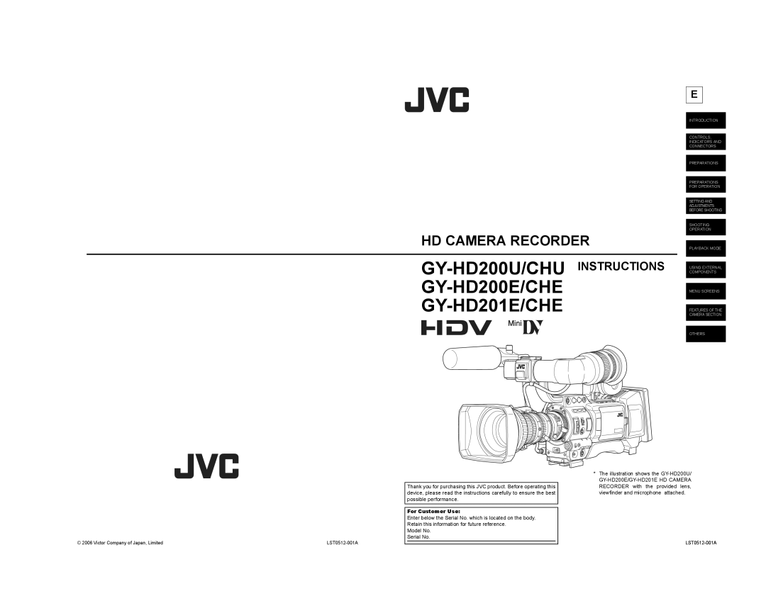
*The illustration shows the