CONTROLS, INDICATORS AND CONNECTORS
Rear Section
1
2
3
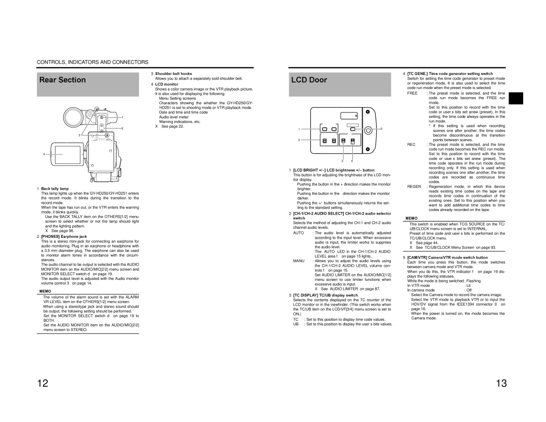
3Shoulder belt hooks
Allows you to attach a separately sold shoulder belt.
4LCD monitor
Shows a color camera image or the VTR playback picture. It is also used for displaying the following:
•Menu Setting screens
•Characters showing the whether the
•Date and time and time code
•Audio level meter
•Warning indications, etc.
X See page 22.
LCD Door
LCD BRIGHT | CAM/VTR | ||
- | + | ||
| |||
1 |
| 5 | |
AUDIO SELECT |
| TC | |
DISPLAY | GENE. | ||
2 | AUTO | TC | FREE |
| MANU | UB | REC |
|
|
| REGEN |
4[TC GENE.] Time code generator setting switch
Switch for setting the time code generator to preset mode or regeneration mode. It is also used to select the time code run mode when the preset mode is selected.
FREE | : The preset mode is selected, and the time |
| code run mode becomes the FREE run |
| mode. |
| Set to this position to record with the time |
| code or user’s bits set anew (preset). In this |
| setting, the time code always operates in the |
| run mode. |
| * If this setting is used when recording |
| scenes one after another, the time codes |
| become discontinuous at the transition |
| points between scenes. |
REC | : The preset mode is selected, and the time |
| code run mode becomes the REC run mode. |
4
1Back tally lamp
This lamp lights up when the
When the tape has run out, or the VTR enters the warning mode, it blinks quickly.
•Use the BACK TALLY item on the OTHERS[1/2] menu screen to select whether or not the lamp should light and the lighting pattern.
X See page 96.
2[PHONES] Earphone jack
This is a stereo
The audio channel to be output is selected with the AUDIO MONITOR item on the AUDIO/MIC[2/2] menu screen and MONITOR SELECT switch d on page 19.
The audio output level is adjusted with the Audio monitor volume control 3 on page 14.
MEMO
•The volume of the alarm sound is set with the ALARM VR LEVEL item on the OTHERS[1/2] menu screen.
•When using a stereotype jack and stereo sound should be output, the following setting should be performed. Set the MONITOR SELECT switch d on page 19 to BOTH.
Set the AUDIO MONITOR item on the AUDIO/MIC[2/2] menu screen to STEREO.
3 4
1[LCD BRIGHT +/–] LCD brightness +/– button
This button is for adjusting the brightness of the LCD mon- itor display.
•Pushing the button in the + direction makes the monitor brighter.
•Pushing the button in the – direction makes the monitor darker.
•Pushing the +/– buttons simultaneously returns the set- ting to the standard setting.
2[CH-1/CH-2 AUDIO SELECT] CH-1/CH-2 audio selector switch
Selects the method of adjusting the
AUTO | : The audio level is automatically adjusted |
| according to the input level. When excessive |
| audio is input, the limiter works to suppress |
| the audio level. |
| The “AUTO” LED in the |
| LEVEL area f on page 15 lights. |
MANU | : Allows you to adjust the audio levels using |
| the |
| trols f on page 15. |
| Set AUDIO LIMITER on the AUDIO/MIC[1/2] |
| menu screen to use limiter functions when |
| excessive audio is input. |
| X See “AUDIO LIMITER” on page 87. |
3[TC DISPLAY] TC/UB display switch
Selects the contents displayed on the TC counter of the LCD monitor or in the viewfinder. (This switch works when the TC/UB item on the LCD/VF[3/4] menu screen is set to ON.)
TC | : Set to this position to display time code values. |
UB | : Set to this position to display the user’s bits values. |
Set to this position to record with the time |
code or user’s bits set anew (preset). The |
time code operates in the run mode during |
recording only. If this setting is used when |
recording scenes one after another, the time |
codes are recorded as continuous time |
codes. |
REGEN : Regeneration mode, in which this device |
reads existing time codes on the tape and |
records time codes in continuation of the |
existing ones. Set to this position when you |
want to add additional time codes to time |
codes already recorded on the tape. |
MEMO
•This switch is enabled when TCG SOURCE on the TC/ UB/CLOCK menu screen is set to INTERNAL.
•Preset of time code and user’s bits is performed on the TC/UB/CLOCK menu.
X See page 44.
X See “TC/UB/CLOCK Menu Screen” on page 93.
5[CAM/VTR] Camera/VTR mode switch button
Each time you press this button, the mode switches between camera mode and VTR mode.
When you do this, the VTR indicator f on page 19 dis- plays the following statuses.
While the mode is being switched : Flashing
In VTR mode | : Lit |
In camera mode | : Off |
•Select the Camera mode to record the camera image.
•Select the VTR mode to playback VTR or to input the HDV/DV signal from the IEEE1394 connector 0 on page 16.
•When the power is turned on, the mode becomes the Camera mode.
12 | 13 |