PREPARATIONS
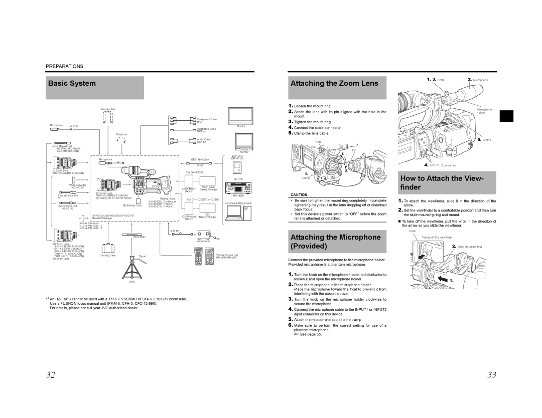
Basic System
Attaching the Zoom Lens
1. 3. Knob | 2. Microphone |
| Shoulder Belt |
Microphone | XLR 3P |
| |
| Earphone |
Focus Manual Unit | |
*1 | |
![]() Component Cable
Component Cable
BNC
Monitor
Composite Cable
RCA pin
![]()
![]() Audio Cable
Audio Cable
RCA pin
1.Loosen the mount ring.
2.Attach the lens with its pin aligned with the hole in the mount.
3.Tighten the mount ring.
4.Connect the cable connector.
5.Clamp the lens cable.
Hole
Microphone holder
5. Clamp
| |
| Microphone |
1/3 Zoom Lens |
|
Th13 × 3.5BRMU (FUJINON) |
|
Wide Converter |
|
| |
Focus Manual Unit | 1/3 Zoom Lens |
Th16 × 5.5BRMU (FUJINON) | |
*1 | (Excluding the CHU/CHE model) |
Zoom Servo Unit | SD Memory Card |
| |
|
|
| Standard Package |
Battery mount
Monitor
|
|
|
|
| HDD Unit | ||
| IEEE1394 Cable |
|
|
| |||
|
|
|
|
|
|
| |
|
|
|
|
|
|
| |
For |
|
|
|
|
|
| |
| DV VTR |
Anton Bauer | Anton Bauer |
Battery Charger | |
Battery |
|
| |
For | |
| |
IDX (Endura) | IDX |
Battery Charger | |
Battery |
|
Pin
Clamp
CAUTION
•Be sure to tighten the mount ring completely. Incomplete tightening may result in the lens dropping off or disturbed back focus.
•Set this device’s power switch to “OFF” before the zoom lens is attached or detached.
4.INPUT1, 2 connector
How to Attach the View- finder
1.To attach the viewfinder, slide it in the direction of the arrow.
2.Set the viewfinder to a comfortable position and then turn the slide mounting ring and mount.
To take off the viewfinder, pull the knob in the direction of |
| Mount Converter |
| (1/2r1/3): |
| (2/3r1/3): |
1/2 Zoom Lens | |
S14 | × 7.3B12U (FUJINON) |
S17 | × 6.6BRM (FUJINON) |
S20 | × 6.4B12U (FUJINON) |
YH16 × 7K12U (CANON) | Carrying Case |
YH19 × 6.7K12U (CANON) | |
2/3 Zoom Lens |
|
Tripod Base
Tripod
Dolly
XLR 4P
AC Adapter
![]() AC
AC
Remote Control Unit
Attaching the Microphone (Provided)
Connect the provided microphone to the microphone holder. Provided microphone is a phantom microphone.
1. Turn the knob on the microphone holder anticlockwise to |
loosen it and open the microphone holder. |
2. Place the microphone in the microphone holder. |
Place the microphone toward the front to prevent it from |
interfering with the cassette cover. |
the arrow as you slide the viewfinder. |
Knob
Taking off the viewfinder
2. Slide mounting ring
![]()
![]()
![]() 1.
1.
*1 An
For details, please consult your JVC authorized dealer.
3. Turn the knob on the microphone holder clockwise to |
secure the microphone. |
4. Connect the microphone cable to the INPUT1 or INPUT2 |
input connector on this device. |
5. Attach the microphone cable to the clamp. |
6. Make sure to perform the correct setting for use of a |
phantom microphone. |
X See page 55. |
32 | 33 |