PREPARATIONS FOR OPERATION
Setting and Displaying the Date and Time (Cont’d)
Setting the Date and Time
1.Display the CLOCK ADJUST menu screen.
Select the CLOCK ADJUST item on the TIME/DATE menu screen.
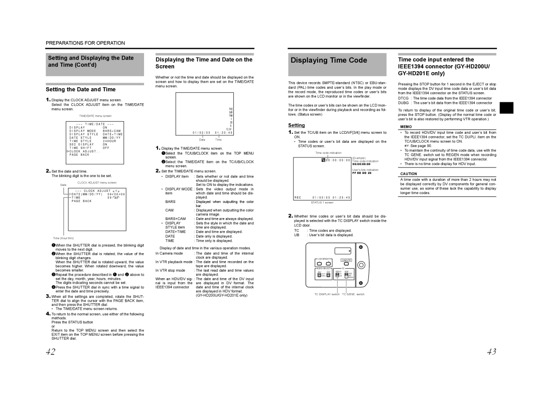
TIME/DATE menu screen
2.Set the date and time.
The blinking digit is the one to be set.
Displaying the Time and Date on the Screen
Whether or not the time and date should be displayed on the screen and how to display them are set on the TIME/DATE menu screen.
Date Time
1.Display the TIME/DATE menu screen.
1Select the TC/UB/CLOCK item on the TOP MENU screen.
2Select the TIME/DATE item on the TC/UB/CLOCK menu screen.
2.Set the TIME/DATE menu screen.
• DISPLAY item : Sets whether or not date and time should be displayed.
Displaying Time Code
This device records
The time codes or user’s bits can be shown on the LCD mon- itor or in the viewfinder during playback and recording as fol- lows. (Status screen)
Setting
1.Set the TC/UB item on the LCD/VF[3/4] menu screen to ON.
•Time codes or user’s bit data are displayed on the STATUS screen.
Time code indication
(Example)
Time code indication
00:00:00:00
User’s bits indication
FF EE DD 20
Time code input entered the IEEE1394 connector
Pressing the STOP button for 1 second in the EJECT or stop mode displays the DV input time code data or user’s bit data from the IEEE1394 connector on the STATUS screen.
DTCG : The time code data from the IEEE1394 connector
DUBG : The user’s bit data from the IEEE1394 connector
To return to display of the original time code or user’s bit, press the STOP button. (Display of the normal time code or user’s bit is also restored by performing VTR operation.)
MEMO
•To record HDV/DV input time code and user’s bit from the IEEE1394 connector, set the TC DUPLI. item on the TC/UB/CLOCK menu screen to ON.
X See page 90.
•To maintain the continuity of time code data, use with the TC GENE. switch set to REGEN mode when recording HDV/DV input signal from the IEEE1394 connector.
•There is no time code display for HDV input.
CAUTION
A time code with a duration of more than 2 hours may not
Date
CLOCK ADJUST menu screen
Set to ON to display the indications.
• DISPLAY MODE : Sets the video output mode in
itemwhich date and time should be dis- played.
be displayed correctly by DV components for general con- sumer use, as some of these lack the capability to display longer time codes.
Time (Hour:Min)
1When the SHUTTER dial is pressed, the blinking digit moves to the next digit.
2When the SHUTTER dial is rotated, the value of the blinking digit changes.
When the SHUTTER dial is rotated upward, the value becomes higher. When rotated downward, the value becomes smaller.
3Repeat the procedure described in 1 and 2 above to set the day, month, year, hours, minutes.
The digits indicating seconds cannot be set.
4Press the SHUTTER dial in sync with a time signal to enter the date and time precisely.
3.When all the settings are completed, rotate the SHUT- TER dial to align the cursor with the PAGE BACK item, and then press the SHUTTER dial.
• The TIME/DATE menu screen returns.
4.To return to the normal screen, use either of the following methods.
Press the STATUS button or
Return to the TOP MENU screen and then select the EXIT item on the TOP MENU screen before pressing the SHUTTER dial.
BARS | : Displayed when outputting the color |
| bar. |
CAM | : Displayed when outputting the color |
| camera image. |
BARS+CAM | : Date and time are always displayed. |
• DISPLAY | : Sets the style in which the date and |
STYLE item | time are displayed. |
DATE+TIME | : Date and time are displayed. |
DATE | : Date only is displayed. |
TIME | : Time only is displayed. |
Display of date and time in the various operation modes.
In Camera mode | : The date and time of the internal |
| clock are displayed. |
In VTR playback mode : The date and time recorded on the tape are displayed.
In VTR stop mode | : The last read date and time values |
| are displayed. |
When an HDV/DV
are displayed in HDV format.
STATUS 1 screen
2.Whether time codes or user’s bit data should be dis- played is selected with the TC DISPLAY switch inside the LCD door.
TC | : Time codes are displayed. | ||
UB | : User’s bit data is displayed. | ||
| LCD BRIGHT | CAM/VTR | |
| - | + | |
|
| ||
| AUDIO SELECT | TC | |
| GENE. | ||
| AUTO | TC | FREE |
| MANU | UB | REC |
|
|
| REGEN |
| TC DISPLAY switch | TC GENE. switch | |
42 | 43 |