MENU SCREENS
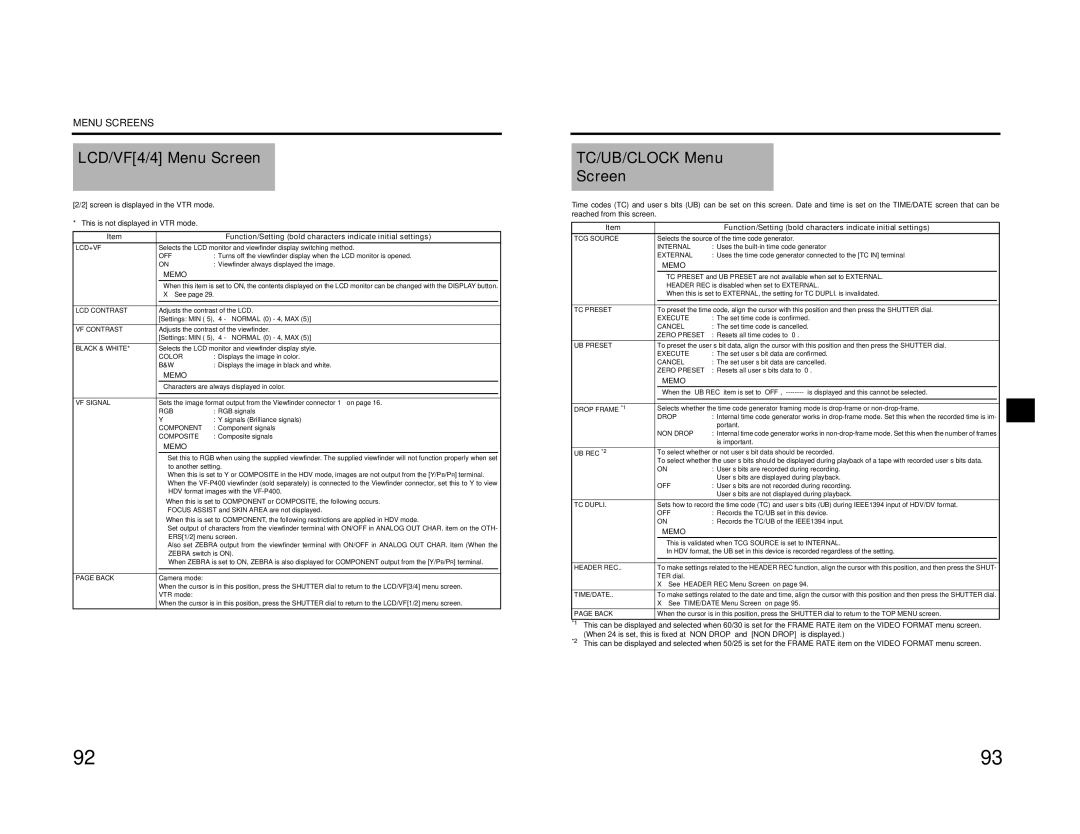
LCD/VF[4/4] Menu Screen
[2/2] screen is displayed in the VTR mode.
* This is not displayed in VTR mode.
Item |
|
| Function/Setting (bold characters indicate initial settings) | |
LCD+VF | Selects the LCD monitor and viewfinder display switching method. | |||
| OFF | : Turns off the viewfinder display when the LCD monitor is opened. | ||
| ON | : Viewfinder always displayed the image. | ||
|
| MEMO |
|
|
|
| When this item is set to ON, the contents displayed on the LCD monitor can be changed with the DISPLAY button. | ||
|
| X See page 29. | ||
|
|
|
| |
|
| |||
LCD CONTRAST | Adjusts the contrast of the LCD. | |||
| [Settings: MIN | |||
VF CONTRAST | Adjusts the contrast of the viewfinder. | |||
| [Settings: MIN | |||
BLACK & WHITE* | Selects the LCD monitor and viewfinder display style. | |||
| COLOR | : Displays the image in color. | ||
| B&W | : Displays the image in black and white. | ||
|
| MEMO |
|
|
|
| Characters are always displayed in color. | ||
|
|
|
| |
|
| |||
VF SIGNAL | Sets the image format output from the Viewfinder connector 1 on page 16. | |||
| RGB | : RGB signals | ||
| Y | : Y signals (Brilliance signals) | ||
| COMPONENT | : Component signals | ||
| COMPOSITE | : Composite signals | ||
|
| MEMO |
|
|
|
| • Set this to RGB when using the supplied viewfinder. The supplied viewfinder will not function properly when set | ||
|
| to another setting. | ||
|
| • When this is set to Y or COMPOSITE in the HDV mode, images are not output from the [Y/PB/PR] terminal. | ||
|
| • When the | ||
|
| HDV format images with the | ||
| When this is set to COMPONENT or COMPOSITE, the following occurs. | |||
|
| • FOCUS ASSIST and SKIN AREA are not displayed. | ||
| When this is set to COMPONENT, the following restrictions are applied in HDV mode. | |||
|
| • Set output of characters from the viewfinder terminal with ON/OFF in ANALOG OUT CHAR. item on the OTH- | ||
|
| ERS[1/2] menu screen. | ||
|
| • Also set ZEBRA output from the viewfinder terminal with ON/OFF in ANALOG OUT CHAR. Item (When the | ||
|
| ZEBRA switch is ON). | ||
|
| When ZEBRA is set to ON, ZEBRA is also displayed for COMPONENT output from the [Y/PB/PR] terminal. | ||
|
|
|
|
|
|
|
|
| |
PAGE BACK | Camera mode: |
|
| |
| When the cursor is in this position, press the SHUTTER dial to return to the LCD/VF[3/4] menu screen. | |||
| VTR mode: |
|
| |
| When the cursor is in this position, press the SHUTTER dial to return to the LCD/VF[1/2] menu screen. | |||
TC/UB/CLOCK Menu
Screen
Time codes (TC) and user’s bits (UB) can be set on this screen. Date and time is set on the TIME/DATE screen that can be reached from this screen.
Item |
| Function/Setting (bold characters indicate initial settings) |
|
TCG SOURCE | Selects the source of the time code generator. |
| |
| INTERNAL | : Uses the |
|
| EXTERNAL | : Uses the time code generator connected to the [TC IN] terminal |
|
| MEMO |
|
|
| • TC PRESET and UB PRESET are not available when set to EXTERNAL. |
| |
| • HEADER REC is disabled when set to EXTERNAL. |
| |
| • When this is set to EXTERNAL, the setting for TC DUPLI. is invalidated. |
| |
|
|
| |
|
|
| |
TC PRESET | To preset the time code, align the cursor with this position and then press the SHUTTER dial. |
| |
| EXECUTE | : The set time code is confirmed. |
|
| CANCEL | : The set time code is cancelled. |
|
| ZERO PRESET | : Resets all time codes to “0”. |
|
UB PRESET | To preset the user’s bit data, align the cursor with this position and then press the SHUTTER dial. |
| |
| EXECUTE | : The set user’s bit data are confirmed. |
|
| CANCEL | : The set user’s bit data are cancelled. |
|
| ZERO PRESET | : Resets all user’s bits data to “0”. |
|
| MEMO |
|
|
| When the “UB REC” item is set to “OFF”, |
| |
|
|
| |
|
|
| |
DROP FRAME *1 | Selects whether the time code generator framing mode is |
| |
| DROP | : Internal time code generator works in |
|
|
| portant. |
|
| NON DROP | : Internal time code generator works in |
|
|
| is important. |
|
UB REC *2 | To select whether or not user’s bit data should be recorded. |
| |
| To select whether the user’s bits should be displayed during playback of a tape with recorded user’s bits data. |
| |
| ON | : User’s bits are recorded during recording. |
|
|
| User’s bits are displayed during playback. |
|
| OFF | : User’s bits are not recorded during recording. |
|
|
| User’s bits are not displayed during playback. |
|
TC DUPLI. | Sets how to record the time code (TC) and user’s bits (UB) during IEEE1394 input of HDV/DV format. |
| |
| OFF | : Records the TC/UB set in this device. |
|
| ON | : Records the TC/UB of the IEEE1394 input. |
|
| MEMO |
|
|
•This is validated when TCG SOURCE is set to INTERNAL.
•In HDV format, the UB set in this device is recorded regardless of the setting.
HEADER REC.. | To make settings related to the HEADER REC function, align the cursor with this position, and then press the SHUT- | |
|
| TER dial. |
|
| X See “HEADER REC Menu Screen” on page 94. |
TIME/DATE.. | To make settings related to the date and time, align the cursor with this position and then press the SHUTTER dial. | |
|
| X See “TIME/DATE Menu Screen” on page 95. |
PAGE BACK | When the cursor is in this position, press the SHUTTER dial to return to the TOP MENU screen. | |
*1 | This can be displayed and selected when 60/30 is set for the FRAME RATE item on the VIDEO FORMAT menu screen. | |
*2 | (When 24 is set, this is fixed at “NON DROP” and “[NON DROP]” is displayed.) | |
This can be displayed and selected when 50/25 is set for the FRAME RATE item on the VIDEO FORMAT menu screen. | ||
92 | 93 |