CONTROLS, INDICATORS AND CONNECTORS
Top Section
MEMO
•When FOCUS ASSIST on the LCD/VF[1/4] menu screen is set to
•This button has the same function as the FOCUS ASSIST button 6 in the Right Side Section.
d[MONITOR SELECT] Audio monitor selector switch
This switch is used to select the monitor sound output and playback sound output from the monitoring speaker 1 on page 14 or the PHONES jack 2 on page 12.
BOTH :
•When you release FAS mode, all of the settings return to their previous modes.
CAUTION
When the power is turned on while the camera is in the FAS mode, it takes about 10 seconds before the automatic adjustment of FAS is completed.
4
3
2
1
d e f g
h i j k
5 6
7
8
9
0
l
a
b
c
X See “LCD/VF[1/4] Menu Screen” on page 86.
8[REC] REC trigger button (start/stop recording) Start and stop recording using this button.
(This works together with the REC trigger button on the right panel and the lens VTR trigger button.)
9[REC LOCK] REC LOCK switch
Slide this switch in the direction of the arrow to lock the [REC] trigger button 8. Use this to prevent unwanted recording.
(The REC trigger button on the right panel and the lens VTR trigger button are not locked.)
0SD memory card cover
When you open this cover, you can insert and remove the SD memory card.
X See “Inserting an SD Memory Card” on page 34. When an SD memory card is loaded
•You can save, call up and reset the menu settings on this device.
•You can initialize (format) an SD memory card.
X See “FILE MANAGE Menu Screen” on page 96.
a[EJECT] Eject switch and LED
Slide this switch to the side to insert or eject a videocas- sette tape.
The LED lights while ejecting is in progress.
MEMO
• It takes a few seconds before the videocassette is |
ejected. Do not close the cassette cover during the eject |
operation. |
can be used to select whether the mixed sound or stereo sound should be output via the PHONES jack. (AUDIO MONITOR item on the AUDIO/MIC[2/2] menu screen)
When AUDIO MONITOR item on the AUDIO/ MIC[2/2] menu screen is set to “STEREO”, only the audio of
X See “Outputting Audio” on page 62.
X See “AUDIO/MIC[2/2] Menu Screen” on page 85.
CAUTION
Make sure to move switches all the way. Do not leave a switch stopped in a midway position. Noise will be gener- ated and operation irregularities will occur.
e[DISPLAY] Display button
•When LCD+VF in the LCD/VF[4/4] menu display is set to OFF, press the DISPLAY button for 2 seconds to switch between the LCD screen and the viewfinder screen.
•When LCD+VF in the LCD/VF[4/4] menu display is set to ON, press the DISPLAY button for 2 seconds to switch the LCD screen ON and OFF. Press the DIS- PLAY button briefly to change the display mode for the LCD screen as follows.
Only image displayed ![]() Characters shown enlarged
Characters shown enlarged ![]() Image and characters displayed
Image and characters displayed ![]()
![]()
All of the previous setting contents are recalled when the FAS mode is cancelled.
h[STOP] Stop button Press to enter the stop mode.
i[REW] Rewind button
Press this button to rewind the tape.
•Pressing this button in the stop or fast forward mode ini- tiates the rewind mode. (Only for VTR mode)
•Pressing this button during playback, still picture play- back or forward search initiates reverse search.
j[PLAY/STILL] Play/still button
Press to start playback. Press to enter the still picture mode during playback, in the stop mode or in the search mode.
Depending on the ambient temperature, if still image play- back mode continues for between 30 seconds and 3 min- utes, it stops automatically. (Tape protect mode)
During still picture playback and search mode, press this button to return to the normal playback mode.
*If the auto tracking is active at the moment the play mode is entered, the playback video will be interfered with digital noise.
k[FF] Fast forward button
Press this button to fast forward the tape.
•Pressing this button in the stop or rewind mode initiates the fast forward mode. (Only for VTR mode)
•Pressing this button during playback, still picture play- back or reverse search initiates forward search.
lScrew holes for mounting accessories
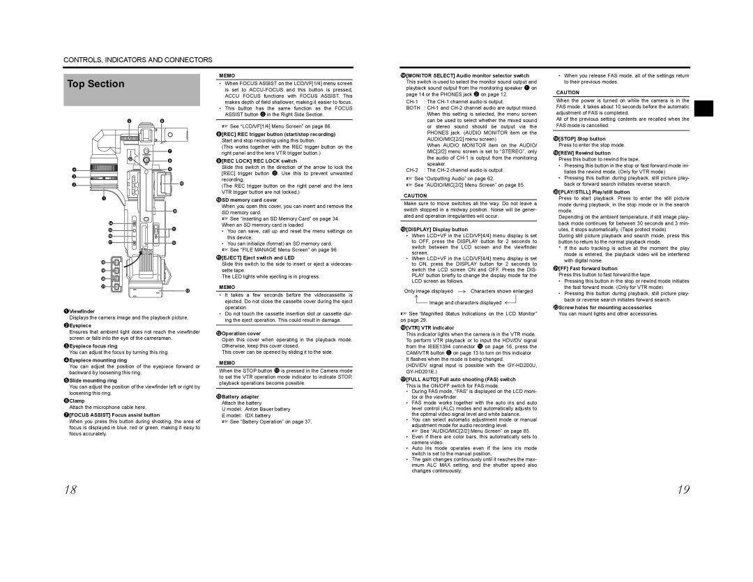
1Viewfinder
Displays the camera image and the playback picture.
2Eyepiece
Ensures that ambient light does not reach the viewfinder screen or falls into the eye of the cameraman.
3Eyepiece focus ring
You can adjust the focus by turning this ring.
4Eyepiece mounting ring
You can adjust the position of the eyepiece forward or backward by loosening this ring.
5Slide mounting ring
You can adjust the position of the viewfinder left or right by loosening this ring.
6Clamp
Attach the microphone cable here.
7[FOCUS ASSIST] Focus assist button
When you press this button during shooting, the area of focus is displayed in blue, red or green, making it easy to focus accurately.
• Do not touch the cassette insertion slot or cassette dur- |
ing the eject operation. This could result in damage. |
bOperation cover
Open this cover when operating in the playback mode. Otherwise, keep this cover closed.
This cover can be opened by sliding it to the side.
MEMO
When the STOP button h is pressed in the Camera mode to set the VTR operation mode indicator to indicate STOP, playback operations become possible.
cBattery adapter Attach the battery.
U model: Anton Bauer battery
E model: IDX battery
X See “Battery Operation” on page 37.
X See “Magnified Status Indications on the LCD Monitor” on page 29.
f[VTR] VTR indicator
This indicator lights when the camera is in the VTR mode. To perform VTR playback or to input the HDV/DV signal from the IEEE1394 connector 0 on page 16, press the CAM/VTR button 5 on page 13 to turn on this indicator.
It flashes when the mode is being changed.
(HDV/DV signal input is possible with the
g[FULL AUTO] Full auto shooting (FAS) switch
This is the ON/OFF switch for FAS mode.
•During FAS mode, “FAS” is displayed on the LCD moni- tor or the viewfinder.
•FAS mode works together with the auto iris and auto level control (ALC) modes and automatically adjusts to the optimal video signal level and white balance.
•You can select automatic adjustment mode or manual adjustment mode for audio recording level.
X See “AUDIO/MIC[2/2] Menu Screen” on page 85.
•Even if there are color bars, this automatically sets to camera video.
•Auto iris mode operates even if the lens iris mode switch is set to the manual position.
•The gain changes continuously until it reaches the max- imum ALC MAX setting, and the shutter speed also changes continuously.
You can mount lights and other accessories.
18 | 19 |