Parallel Interface
Interface Signals
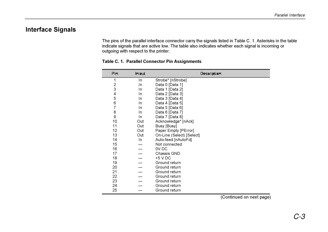
The pins of the parallel interface connector carry the signals listed in Table C. 1. Asterisks in the table indicate signals that are active low. The table also indicates whether each signal is incoming or outgoing with respect to the printer.
Table C. 1. Parallel Connector Pin Assignments
Pin | In/out | Description |
1 | In | Strobe* [nStrobe] |
2 | In | Data 0 [Data 1] |
3 | In | Data 1 [Data 2] |
4 | In | Data 2 [Data 3] |
5 | In | Data 3 [Data 4] |
6 | In | Data 4 [Data 5] |
7 | In | Data 5 [Data 6] |
8 | In | Data 6 [Data 7] |
9 | In | Data 7 [Data 8] |
10 | Out | Acknowledge* [nAck] |
11 | Out | Busy [Busy] |
12 | Out | Paper Empty [PError] |
13 | Out | |
14 | In | |
15 | — | Not connected |
16 | — | 0V DC |
17 | — | Chassis GND |
18 | — | +5 V DC |
19 | — | Ground return |
20 | — | Ground return |
21 | — | Ground return |
22 | — | Ground return |
23 | — | Ground return |
24 | — | Ground return |
25 | — | Ground return |