Gas Heat Control Mode
THERMOSTAT
DEMAND
SYSTEM
IDLE
Differential less than 2nd stage
differential NO
?
YES
Starting firing rate as determined by variable capacity algorithm (35 to 100%)
Differential less than 2nd stage
differential NO
?
YES
Continue at
starting firing rate
T’stat demand
NO satisfied
?
YES
Differential less than 3rd stage
differential NO
?
YES
Increase firing rate to calculated 2nd stage firing rate
T’stat
demand sat−
isfied in less than
YES 5 minutes
?
NO
Differential less than 3rd stage
differential NO
?
YES
Firing rate increased by 5% every 5 ![]() minutes up to 100% firing rate
minutes up to 100% firing rate
T’stat demand
satisfied NO
?
YES
Differential |
| Increase firing | |
| rate to 100% | ||
less than 4th stage |
| ||
| until thermostat | ||
NO | |||
differential | |||
demand is |
?satisfied
YES
Increase firing rate to calculated 3rd stage firing rate
T’stat
demand sat−
isfied in less than
YES 5 minutes
?
NO
Differential less than 4th stage
differential NO
?
YES
Firing rate increased by
5% every 5 minutes up to
100% firing rate
T’stat demand satisfied NO
?
YES
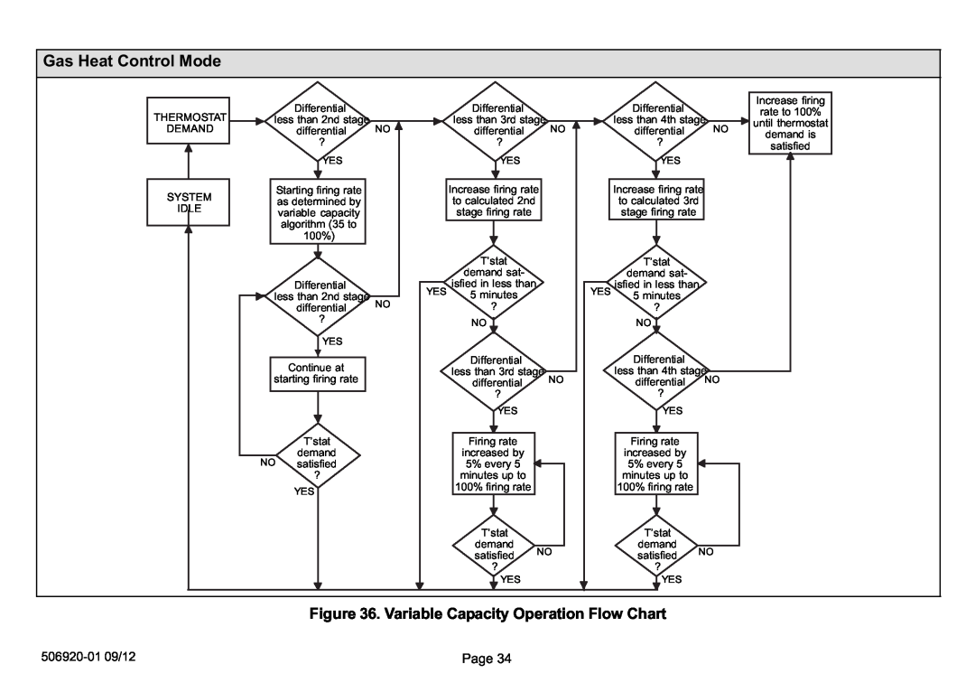
Figure 36. Variable Capacity Operation Flow Chart
506920−01 09/12 | Page 34 |