Configuring heat strips on Air Handler Control (AHC)
IMPORTANT: After electric heat strips are installed, the Air Handler Control (AHC) must be manually configured to detect the number of electric heat sections. (SEE ALSO 506181−01 for complete configuration guide.)
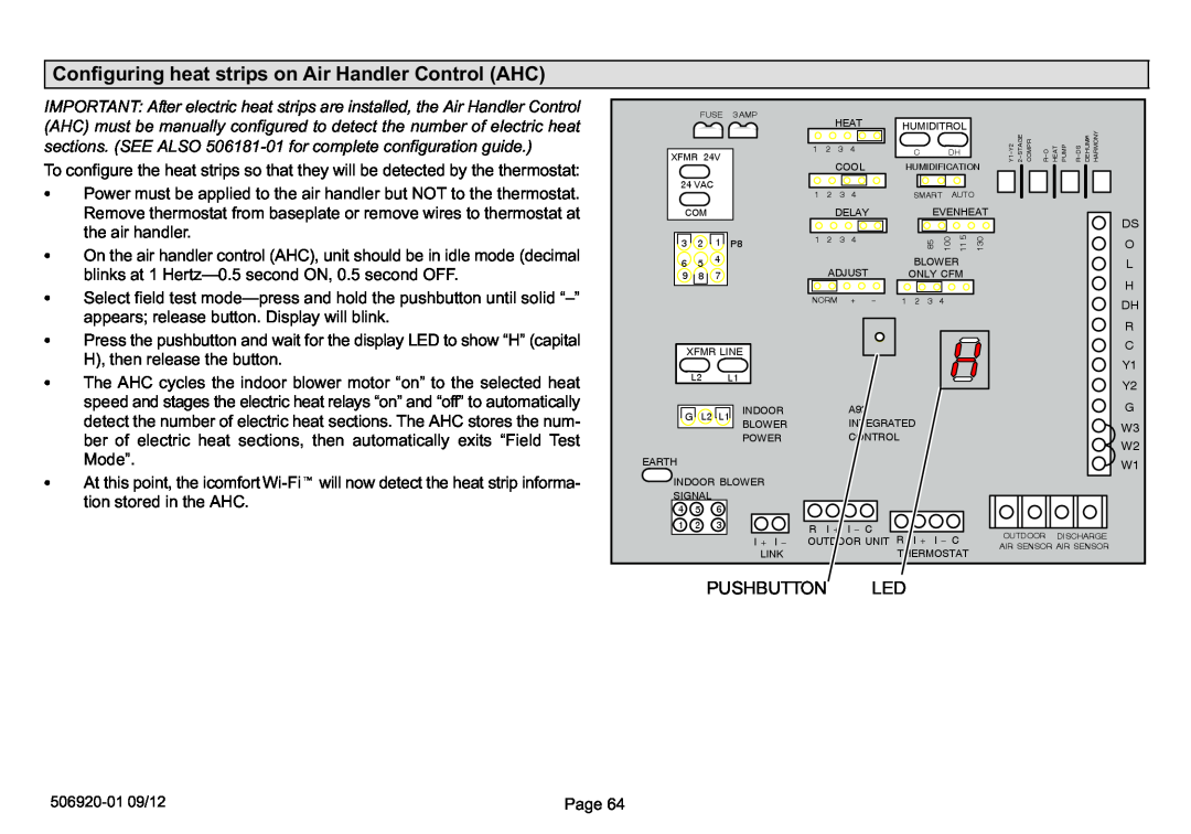
To configure the heat strips so that they will be detected by the thermostat:
SPower must be applied to the air handler but NOT to the thermostat. Remove thermostat from baseplate or remove wires to thermostat at the air handler.
SOn the air handler control (AHC), unit should be in idle mode (decimal blinks at 1 Hertz.
SSelect field test mode
appears; release button. Display will blink.
SPress the pushbutton and wait for the display LED to show H), then release the button.
SThe AHC cycles the indoor blower motor
speed and stages the electric heat relays f" to automatically detect the number of electric heat sections. The AHC stores the num- ber of electric heat sections, then automatically exits Test Mode".
SAt this point, the icomfort
| FUSE | 3 AMP |
|
| HEAT |
|
|
|
|
|
|
|
|
|
|
|
|
| ||
|
|
|
|
|
|
| HUMIDITROL |
|
|
|
|
|
|
|
| |||||
|
|
|
|
|
|
|
|
|
|
|
|
|
|
|
| HARMONY | ||||
XFMR 24V |
| 1 | 2 | 3 | 4 |
|
| C | DH |
| Y1−Y2 | 2−STAGE COMPR | R−O | HEAT PUMP | R−DS | DEHUMOR | ||||
|
|
|
|
|
|
|
| |||||||||||||
|
|
| COOL |
| HUMIDIFICATION | |||||||||||||||
|
|
|
|
|
|
|
|
|
|
|
|
|
| |||||||
24 VAC |
|
| 1 | 2 | 3 | 4 |
|
| SMART | AUTO |
|
|
|
|
|
|
|
| ||
|
|
|
|
|
|
|
|
|
|
|
|
|
| |||||||
COM |
|
|
|
| DELAY |
|
| EVENHEAT |
|
|
|
|
|
| DS | |||||
|
|
|
|
|
|
|
|
|
|
|
|
|
|
|
|
|
|
|
| |
3 | 2 | 1 | P8 | 1 | 2 | 3 | 4 |
|
| 85 | 100 | 11 5 | 130 |
|
|
|
|
|
| O |
|
|
|
|
|
|
|
|
|
|
|
| |||||||||
6 | 5 | 4 |
|
| ADJUST |
|
| BLOWER |
|
|
|
|
|
|
| L | ||||
9 | 8 | 7 |
|
|
|
| ONLY CFM |
|
|
|
|
|
|
| H | |||||
|
|
|
|
|
|
|
|
|
|
|
|
|
|
|
|
|
|
|
| |
|
|
|
| NORM | + | − | 1 | 2 3 | 4 |
|
|
|
|
|
|
|
| DH | ||
|
|
|
|
|
|
|
|
|
|
|
|
|
|
|
|
|
|
|
| |
|
|
|
|
|
|
|
|
|
|
|
|
|
|
|
|
|
|
|
| R |
XFMR LINE |
|
|
|
|
|
|
|
|
|
|
|
|
|
|
|
| C | |||
|
|
|
|
|
|
|
|
|
|
|
|
|
|
|
| Y1 | ||||
L2 |
|
|
|
|
|
|
|
|
|
|
|
|
|
|
|
|
|
| ||
L1 |
|
|
|
|
|
|
|
|
|
|
|
|
|
|
|
| Y2 | |||
|
|
|
|
|
|
|
|
|
|
|
|
|
|
|
|
|
|
|
| |
G | L2 | L1 | INDOOR |
|
|
| A92 |
|
|
|
|
|
|
|
|
|
|
|
| G |
|
|
|
|
|
|
|
|
|
|
|
|
|
|
|
| |||||
|
|
| BLOWER |
|
|
| INTEGRATED |
|
|
|
|
|
|
|
|
| W3 | |||
|
|
| POWER |
|
|
| CONTROL |
|
|
|
|
|
|
|
|
|
| |||
|
|
|
|
|
|
|
|
|
|
|
|
|
|
|
| W2 | ||||
|
|
|
|
|
|
|
|
|
|
|
|
|
|
|
|
|
|
|
| |
EARTH |
|
|
|
|
|
|
|
|
|
|
|
|
|
|
|
|
|
|
| W1 |
INDOOR BLOWER |
|
|
|
|
|
|
|
|
|
|
|
|
|
|
|
|
| |||
SIGNAL |
|
|
|
|
|
|
|
|
|
|
|
|
|
|
|
|
|
|
| |
4 | 5 | 6 |
|
|
|
|
|
|
|
|
|
|
|
|
|
|
|
|
|
|
1 | 2 | 3 |
| R | I + | I − C |
|
|
|
|
| OUTDOOR |
|
|
|
| ||||
|
|
|
| R | I + | I − C |
| DISCHARGE | ||||||||||||
|
|
| I + I − | OUTDOOR UNIT |
| |||||||||||||||
|
|
|
| AIR SENSOR AIR SENSOR | ||||||||||||||||
|
|
| LINK |
|
|
|
|
| THERMOSTAT |
| ||||||||||
|
|
|
|
|
|
|
|
|
|
|
|
|
|
|
| |||||
| PUSHBUTTON |
|
| LED |
|
|
|
|
|
|
|
|
|
|
| |||||
506920−01 09/12 | Page 64 |