5. Features and Functions
3 REAR PANEL
|
|
|
| 1 | 2 |
|
|
| REMOTE |
| |
| VIDEO |
|
|
|
|
|
|
|
|
| AC LINE |
|
|
|
| IMPEDANCE |
|
R | G/G+SYNC | B | RGB |
| |
IN |
|
|
| 75Ω |
|
|
|
|
|
| |
|
|
|
| HIGH |
|
|
|
|
| SYNC. |
|
OUT |
|
|
| 75Ω |
|
|
|
|
|
| |
|
|
|
| HIGH |
|
R | G/G+SYNC | B |
|
|
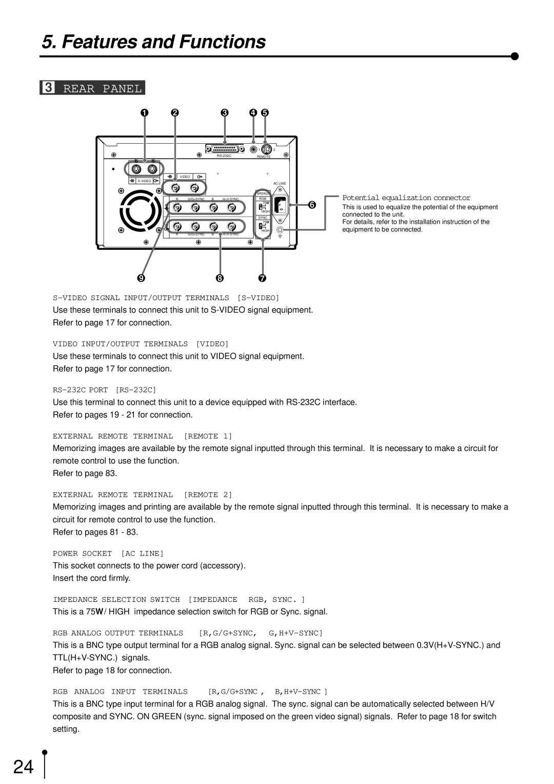
Potential equalization connector
This is used to equalize the potential of the equipment connected to the unit.
For details, refer to the installation instruction of the equipment to be connected.
1
Use these terminals to connect this unit to
2 VIDEO INPUT/OUTPUT TERMINALS [VIDEO]
Use these terminals to connect this unit to VIDEO signal equipment.
Refer to page 17 for connection.
3
Use this terminal to connect this unit to a device equipped with
4EXTERNAL REMOTE TERMINAL [REMOTE 1]
Memorizing images are available by the remote signal inputted through this terminal. It is necessary to make a circuit for remote control to use the function.
Refer to page 83.
5EXTERNAL REMOTE TERMINAL [REMOTE 2]
Memorizing images and printing are available by the remote signal inputted through this terminal. It is necessary to make a circuit for remote control to use the function.
Refer to pages 81 - 83.
6POWER SOCKET [AC LINE]
This socket connects to the power cord (accessory). Insert the cord firmly.
7 | IMPEDANCE SELECTION SWITCH [IMPEDANCE RGB, SYNC. ] | ||
| This is a 75Ω / HIGH impedance selection switch for RGB or Sync. signal. | ||
8 | RGB ANALOG OUTPUT TERMINALS | [R,G/G+SYNC, |
|
| This is a BNC type output terminal for a RGB analog signal. Sync. signal can be selected between | ||
|
|
| |
| Refer to page 18 for connection. |
|
|
9 | RGB ANALOG INPUT TERMINALS | [R,G/G+SYNC , | |
This is a BNC type input terminal for a RGB analog signal. The sync. signal can be automatically selected between H/V composite and SYNC. ON GREEN (sync. signal imposed on the green video signal) signals. Refer to page 18 for switch setting.
24
