8. Printing Procedures (Special prints)
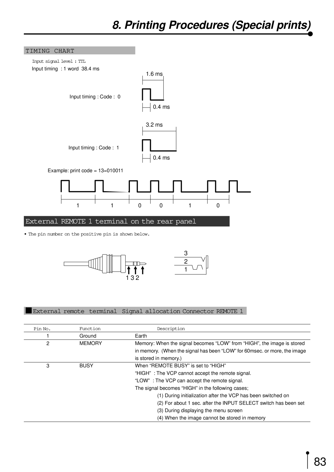
TIMING CHART
Input signal level : TTL
Input timing : 1 word 38.4 ms
Input timing : Code : “0”
Input timing : Code : “1”
Example: print code = 13=010011
11
1.6 ms
![]()
![]() 0.4 ms
0.4 ms
3.2 ms
![]()
![]() 0.4 ms
0.4 ms
0 0 1
0
External REMOTE 1 terminal on the rear panel
• The pin number on the positive pin is shown below.
3
2 ![]()
![]()
![]() 1 1 3 2
1 1 3 2
1External remote terminal Signal allocation Connector REMOTE 1
Pin No. | Function | Description | |
1 | Ground | Earth |
|
|
|
| |
2 | MEMORY | Memory: When the signal becomes “LOW” from “HIGH”, the image is stored | |
|
| in memory. (When the signal has been “LOW” for 60msec. or more, the image | |
|
| is stored in memory.) | |
|
|
| |
3 | BUSY | When “REMOTE BUSY” is set to “HIGH” | |
|
| “HIGH” : The VCP cannot accept the remote signal. | |
|
| “LOW” : The VCP can accept the remote signal. | |
|
| The signal becomes “HIGH” in the following cases; | |
|
| (1) | During initialization after the VCP has been switched on |
|
| (2) | For about 1 sec. after the INPUT SELECT switch has been set |
|
| (3) | During displaying the menu screen |
|
| (4) | When the image cannot be stored in memory |
|
|
|
|
83