8. Printing Procedures (Special prints)
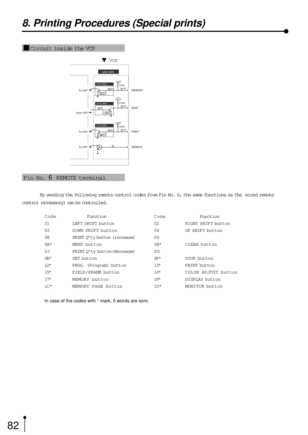
1Circuit inside the VCP
}VCP
User side
|
| DC5V |
| DTC124EK | 10KΩ |
|
| |
To VCP | 22KΩ | 100 Ω 2 MEMORY |
| 22KΩ |
|
|
| DC5V |
| DTC124EK | 2.2KΩ |
| 22KΩ | 100 Ω 4 BUSY |
From VCP | 22KΩ |
|
|
| DC5V |
| DTC124EK | 10KΩ |
|
| |
To VCP | 22KΩ | 100 Ω 5 PRINT |
| 22KΩ |
|
To VCP | 1K | 6 REMOTE |
|
Pin No. 6 REMOTE terminal
By sending the following remote control codes from Pin No. 6, the same functions as the wired remote
control (accessory) can be controlled.
Code | Function | Code | Function |
01 | LEFT SHIFT button | 02 | RIGHT SHIFT button |
03 | DOWN SHIFT button | 04 | UP SHIFT button |
08 | PRINT Q’ty button (increase) | 09 |
|
0A* | MENU button | 0B* | CLEAR button |
0C | PRINT Q’ty button(decrease) | 0D |
|
0E* | SET button | 0F* | STOP button |
12* | PROG. (Program) button | 13* | PRINT button |
15* | FIELD/FRAME button | 16* | COLOR ADJUST button |
17* | MEMORY button | 18* | DISPLAY button |
1C* | MEMORY PAGE button | 1D* | MONITOR button |
In case of the codes with * mark, 5 words are sent.
82