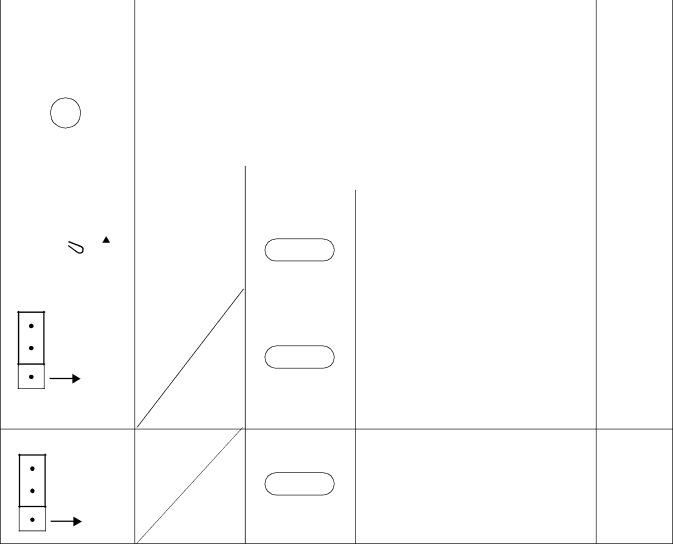
(3) Switch Settings
Switch Settings
SWITCH NAME |
| SWITCH |
|
|
| SETTING |
|
|
|
|
| FUNCTION |
|
|
| CHECK | ||||||||||||||
| NUMBER |
|
|
| POSITION |
|
|
|
|
|
| |||||||||||||||||||
|
|
|
|
|
|
|
|
|
|
|
|
|
|
|
|
|
|
|
|
|
|
|
| |||||||
|
|
|
|
|
|
|
|
|
|
|
|
|
|
|
|
|
|
|
|
|
|
|
|
|
| |||||
SENSE |
| 4 - F |
| Set the switch to match the AP Number (04 - 15) to be set by | ||||||||||||||||||||||||||
(Rotary SW) |
|
|
| CM05. |
|
|
|
|
|
|
|
|
|
|
|
|
|
|
| |||||||||||
|
|
|
|
|
|
|
|
|
|
|
|
|
|
|
|
|
|
|
|
|
|
|
|
|
|
|
|
|
| |
|
|
|
|
|
|
|
|
|
|
|
|
|
|
|
|
|
|
|
|
|
|
|
|
|
|
|
|
| ||
|
|
|
|
|
|
|
|
|
|
|
|
|
|
|
|
|
|
|
|
|
|
|
|
|
|
|
|
| ||
|
|
|
|
|
|
|
|
|
| AP NO. | 04 |
| 05 | 06 |
| 07 |
| 08 | 09 | 10 | 11 |
| 12 |
| 13 | 14 | 15 |
| ||
|
|
|
|
|
|
|
|
| ||||||||||||||||||||||
|
|
|
|
|
|
|
|
|
|
|
|
|
|
|
|
|
|
|
|
|
|
|
|
|
|
|
|
| ||
|
|
|
|
|
|
|
|
|
| SW NO. | 4 |
| 5 | 6 |
| 7 |
| 8 | 9 | A | B |
| C |
| D | E | F |
| ||
Note 1 | ||||||||||||||||||||||||||||||
|
|
|
|
|
|
|
|
|
|
|
|
|
|
|
|
|
|
|
|
| ||||||||||
|
|
|
|
|
|
|
|
|
|
|
|
|
|
|
|
|
|
|
|
| ||||||||||
|
|
|
|
|
|
|
|
|
|
|
|
|
|
|
|
|
|
|
|
|
|
|
|
|
|
|
|
|
| |
|
|
|
|
|
|
|
|
| 0 - 3 |
|
|
|
|
|
|
|
|
| Not used |
|
|
|
|
|
| |||||
|
|
|
|
|
|
|
|
|
|
|
|
|
|
|
|
|
|
|
|
|
|
|
|
|
|
|
|
|
| |
MB(Toggle SW) |
|
|
| UP |
|
|
|
|
| For |
|
|
|
|
|
|
|
| ||||||||||||
|
|
|
|
|
|
|
|
|
|
|
|
|
|
|
|
|
|
|
|
|
|
|
|
|
|
|
|
|
| |
|
|
|
|
|
|
| ON |
|
|
|
|
|
|
|
|
|
| For normal operation |
|
|
|
|
|
| ||||||
|
|
|
|
|
|
|
|
|
|
|
|
|
|
|
|
|
|
|
|
|
|
| ||||||||
|
|
|
|
|
|
|
|
|
|
|
|
|
|
|
|
|
|
|
|
|
|
|
|
|
|
|
| |||
|
|
|
|
|
|
|
|
|
|
|
|
|
| DOWN |
|
|
|
|
|
|
|
|
|
|
|
|
| |||
|
|
|
|
|
|
|
|
|
|
|
|
|
|
|
|
|
|
|
|
|
|
|
|
|
|
| ||||
|
|
|
|
|
|
|
|
|
|
|
|
|
|
|
|
|
|
|
|
|
|
|
|
|
|
| ||||
Note 2 |
|
|
|
|
|
|
|
|
|
|
|
|
|
|
|
|
|
|
|
|
| |||||||||
|
|
|
|
|
|
|
|
|
|
|
|
|
|
|
|
|
|
|
|
|
|
|
|
|
|
|
|
|
| |
JP0 (Jumper pin) |
|
|
|
|
|
|
|
|
|
| For normal operation |
|
|
|
|
|
| |||||||||||||
UP
Front
Note 3
JP2 (Jumper pin) | For normal operation |
UP
Front
The figure in the SWITCH NAME column and the position in  in the SETTING POSITION col- umn indicate the standard setting of the switch. When the switch is not set as shown by the figure and
  , the setting of the switch varies with the system concerned.
Note 1: Set the groove on the switch knob to the desired switch position.
Note 2: When the power is on, flip the MB switch to ON (UP position) before plugging/unplugging the circuit card.
Note 3: Do not touch the JP0. If the jumper is pulled off, the data in the memory of the ME00 card is cleared.
Page 83
Revision 2.0
