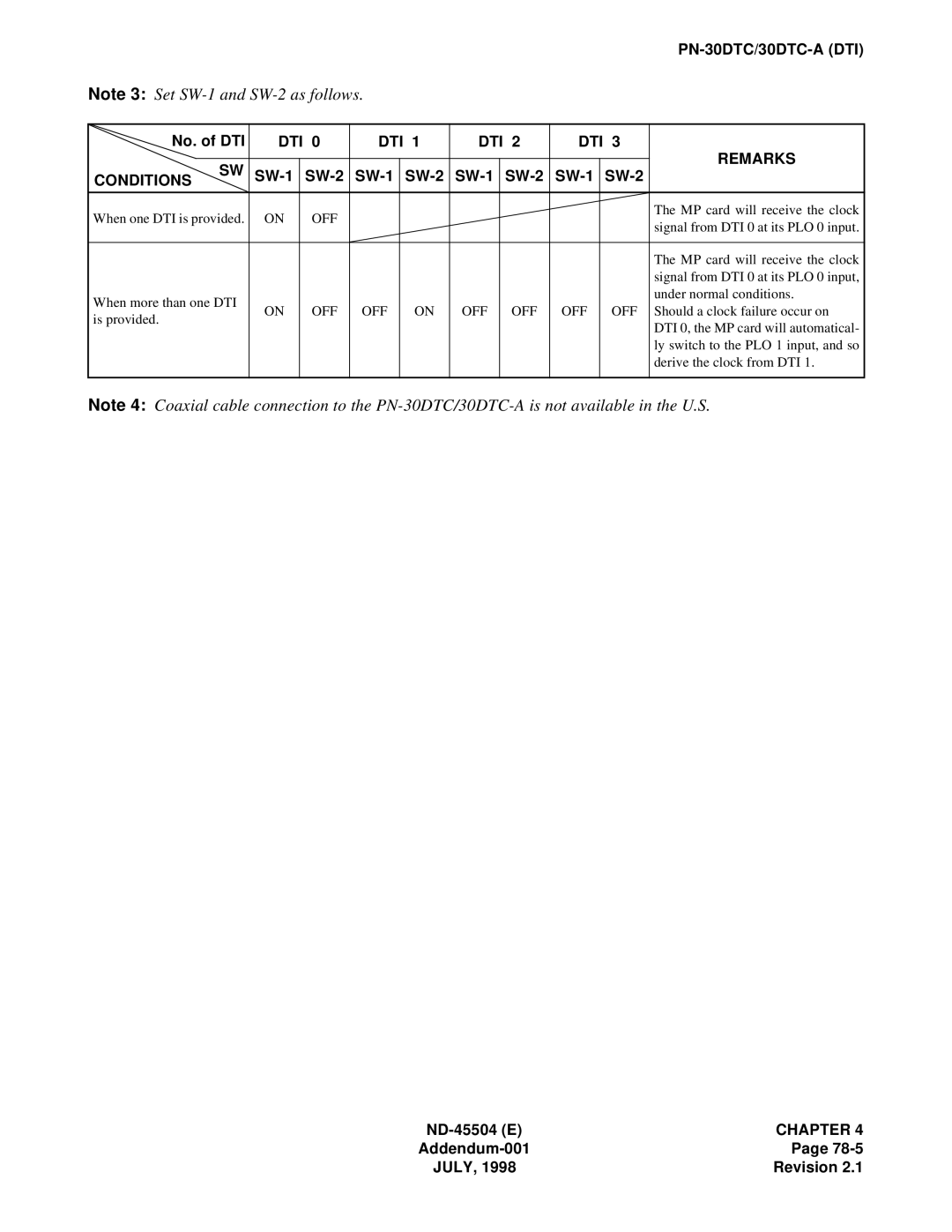
Note 3: Set
No. of DTI | DTI 0 | DTI 1 | DTI 2 | DTI 3 | REMARKS | ||||||
|
|
|
|
|
|
|
|
|
| ||
CONDITIONS SW |
|
| |||||||||
| |||||||||||
When one DTI is provided. | ON | OFF |
|
|
|
|
|
| The MP card will receive the clock | ||
|
|
|
|
|
| signal from DTI 0 at its PLO 0 input. | |||||
|
|
|
|
|
|
|
|
|
| ||
|
|
|
|
|
|
|
|
|
|
| |
|
|
|
|
|
|
|
|
|
| The MP card will receive the clock | |
|
|
|
|
|
|
|
|
|
| signal from DTI 0 at its PLO 0 input, | |
When more than one DTI |
|
|
|
|
|
|
|
| under normal conditions. | ||
ON | OFF | OFF | ON | OFF | OFF | OFF | OFF | Should a clock failure occur on | |||
is provided. | |||||||||||
|
|
|
|
|
|
|
| DTI 0, the MP card will automatical- | |||
|
|
|
|
|
|
|
|
|
| ||
|
|
|
|
|
|
|
|
|
| ly switch to the PLO 1 input, and so | |
|
|
|
|
|
|
|
|
|
| derive the clock from DTI 1. | |
|
|
|
|
|
|
|
|
|
|
| |
Note 4: Coaxial cable connection to the
CHAPTER 4 | |
Page | |
JULY, 1998 | Revision 2.1 |
