|
|
|
|
|
|
|
|
|
|
|
|
|
|
|
|
| |||
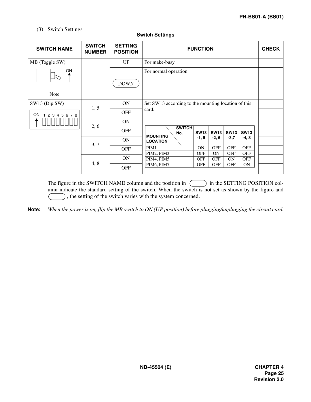
(3) | Switch Settings |
| Switch Settings |
|
|
|
|
|
|
| |||||||||
|
|
|
|
|
|
|
|
|
|
|
|
|
|
|
|
| |||
|
|
|
|
|
|
|
|
|
|
|
|
|
|
|
|
|
|
|
|
|
| SWITCH NAME |
| SWITCH | SETTING |
|
| FUNCTION |
|
|
| CHECK | |||||||
|
|
| NUMBER | POSITION |
|
|
|
|
| ||||||||||
|
|
|
|
|
|
|
|
|
|
|
|
|
|
|
|
|
| ||
|
|
|
|
|
|
|
|
|
|
|
|
|
|
|
|
|
|
| |
| MB (Toggle SW) |
|
| UP | For |
|
|
|
|
|
|
| |||||||
|
|
|
|
| ON |
|
|
|
|
|
|
|
|
|
|
|
| ||
|
|
|
|
|
|
| DOWN | For normal operation |
|
|
|
|
|
|
| ||||
|
|
|
|
|
|
|
|
|
|
|
|
| |||||||
|
|
|
|
|
|
|
|
|
|
|
|
|
|
|
|
|
|
| |
|
|
|
|
|
|
|
|
|
|
|
|
|
|
|
|
|
|
| |
|
|
| Note |
|
|
|
|
|
|
|
|
|
|
| |||||
|
|
|
|
|
|
|
|
|
|
|
|
|
|
| |||||
|
|
|
|
|
|
|
|
|
|
|
|
|
|
|
|
|
| ||
| SW13 (Dip SW) |
| 1, 5 | ON | Set SW13 according to the mounting location of this |
| |||||||||||||
|
|
|
|
|
|
|
|
|
| card. |
|
|
|
|
|
|
| ||
|
|
|
|
|
|
|
|
| OFF |
|
|
|
|
|
|
| |||
| ON | 1 2 3 4 5 6 7 8 |
|
|
|
|
|
|
|
|
|
| |||||||
|
|
|
|
|
|
|
|
|
|
|
|
| |||||||
|
|
|
|
|
|
|
|
|
|
|
|
|
| ||||||
|
|
|
|
|
|
|
|
| 2, 6 | ON |
|
|
|
|
|
|
|
|
|
|
|
|
|
|
|
|
|
|
|
|
|
|
|
|
|
|
| ||
|
|
|
|
|
|
|
|
|
|
|
|
|
|
|
|
|
|
| |
|
|
|
|
|
|
|
|
|
| OFF |
| SWITCH | SW13 | SW13 | SW13 | SW13 |
|
| |
|
|
|
|
|
|
|
|
|
|
|
| ||||||||
|
|
|
|
|
|
|
|
|
|
| No. |
|
|
| |||||
|
|
|
|
|
|
|
|
|
|
|
|
|
|
| |||||
|
|
|
|
|
|
|
|
|
|
|
| MOUNTING |
|
|
| ||||
|
|
|
|
|
|
|
|
|
| ON |
|
|
| ||||||
|
|
|
|
|
|
|
|
|
|
| LOCATION |
|
|
| |||||
|
|
|
|
|
|
|
|
| 3, 7 |
|
|
|
|
|
|
|
| ||
|
|
|
|
|
|
|
|
|
|
|
|
|
|
|
|
|
|
| |
|
|
|
|
|
|
|
|
| OFF |
| PIM1 |
| ON | OFF | OFF | OFF |
|
| |
|
|
|
|
|
|
|
|
|
|
|
|
|
| ||||||
|
|
|
|
|
|
|
|
|
|
|
| PIM2, PIM3 |
| OFF | ON | OFF | OFF |
|
|
|
|
|
|
|
|
|
|
|
| ON |
| ||||||||
|
|
|
|
|
|
|
|
| 4, 8 |
| PIM4, PIM5 |
| OFF | OFF | ON | OFF |
|
| |
|
|
|
|
|
|
|
|
|
|
| PIM6, PIM7 |
| OFF | OFF | OFF | ON |
|
| |
|
|
|
|
|
|
|
|
| OFF |
| |||||||||
|
|
|
|
|
|
|
|
|
|
|
|
|
|
|
|
|
|
| |
|
|
|
|
|
|
|
|
|
|
|
|
|
|
|
|
|
|
|
|
The figure in the SWITCH NAME column and the position in  in the SETTING POSITION col- umn indicate the standard setting of the switch. When the switch is not set as shown by the figure and
  , the setting of the switch varies with the system concerned.
Note: When the power is on, flip the MB switch to ON (UP position) before plugging/unplugging the circuit card.
Page 25
Revision 2.0