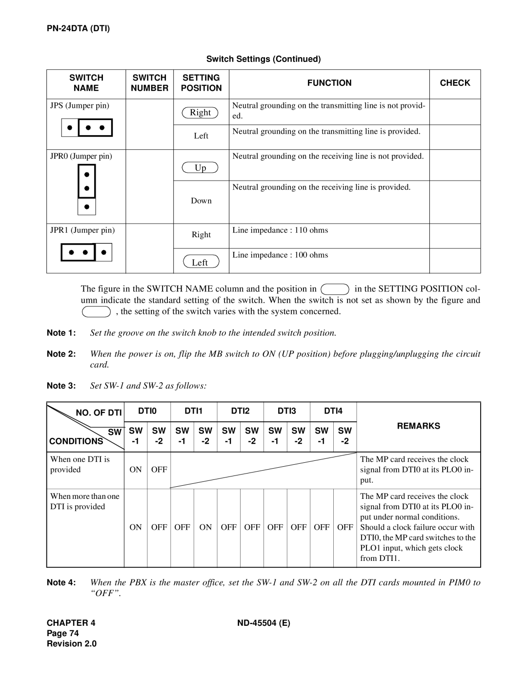
Switch Settings (Continued)
| SWITCH | SWITCH | SETTING | FUNCTION | CHECK | |||
| NAME | NUMBER | POSITION | |||||
|
|
| ||||||
|
|
|
|
|
|
|
|
|
JPS (Jumper pin) |
| Right | Neutral grounding on the transmitting line is not provid- |
| ||||
|
|
|
|
|
| ed. |
| |
|
|
|
|
|
|
|
|
|
|
|
|
|
|
| Left | Neutral grounding on the transmitting line is provided. |
|
|
|
|
|
|
|
|
| |
|
|
|
|
|
|
|
|
|
JPR0 (Jumper pin) |
|
| Neutral grounding on the receiving line is not provided. |
| ||||
|
|
|
|
|
| Up |
|
|
|
|
|
|
|
|
|
| |
|
|
|
|
|
|
|
|
|
|
|
|
|
|
|
| Neutral grounding on the receiving line is provided. |
|
|
|
|
|
|
| Down |
|
|
|
|
|
|
|
|
|
| |
|
|
|
|
|
|
|
|
|
|
|
|
|
|
|
|
|
|
JPR1 (Jumper pin) |
| Right | Line impedance : 110 ohms |
| ||||
|
|
|
|
|
|
|
| |
Line impedance : 100 ohms
Left
The figure in the SWITCH NAME column and the position in  in the SETTING POSITION col- umn indicate the standard setting of the switch. When the switch is not set as shown by the figure and
  , the setting of the switch varies with the system concerned.
Note 1: Set the groove on the switch knob to the intended switch position.
Note 2: When the power is on, flip the MB switch to ON (UP position) before plugging/unplugging the circuit card.
Note 3: Set
NO. OF DTI |
| DTI0 | DTI1 | DTI2 | DTI3 | DTI4 |
| ||||||
|
|
|
|
|
|
|
|
|
|
|
|
| REMARKS |
|
|
| SW | SW | SW | SW | SW | SW | SW | SW | SW | SW | |
| SW |
| |||||||||||
|
|
| |||||||||||
CONDITIONS |
| ||||||||||||
|
|
|
|
|
|
|
|
|
|
|
|
|
|
When one DTI is |
|
|
|
|
|
|
|
|
|
|
| The MP card receives the clock | |
provided |
| ON | OFF |
|
|
|
|
|
|
|
| signal from DTI0 at its PLO0 in- | |
|
|
|
|
|
|
|
|
|
|
|
|
| put. |
|
|
|
|
|
|
|
|
|
|
|
|
|
|
When more than one |
|
|
|
|
|
|
|
|
|
|
| The MP card receives the clock | |
DTI is provided |
|
|
|
|
|
|
|
|
|
|
| signal from DTI0 at its PLO0 in- | |
|
|
|
|
|
|
|
|
|
|
|
|
| put under normal conditions. |
|
|
| ON | OFF | OFF | ON | OFF | OFF | OFF | OFF | OFF | OFF | Should a clock failure occur with |
|
|
|
|
|
|
|
|
|
|
|
|
| DTI0, the MP card switches to the |
|
|
|
|
|
|
|
|
|
|
|
|
| PLO1 input, which gets clock |
|
|
|
|
|
|
|
|
|
|
|
|
| from DTI1. |
|
|
|
|
|
|
|
|
|
|
|
|
|
|
Note 4: When the PBX is the master office, set the
CHAPTER 4 |
Page 74
Revision 2.0