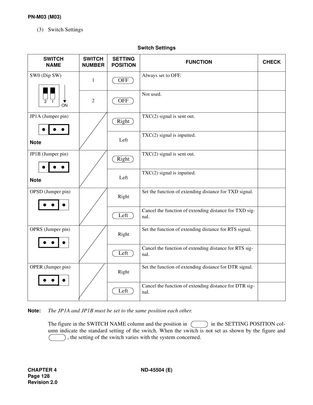
(3) Switch Settings
Switch Settings
|
| SWITCH | SWITCH | SETTING | FUNCTION | CHECK | |||||||
|
| NAME | NUMBER | POSITION | |||||||||
|
|
|
| ||||||||||
|
|
|
|
|
|
|
|
|
|
|
|
|
|
SW0 (Dip SW) | 1 | OFF | Always set to OFF. |
| |||||||||
|
|
|
|
|
|
|
|
|
|
|
| ||
|
|
|
|
|
|
|
|
|
|
|
|
|
|
|
|
|
|
|
|
|
|
|
|
|
|
|
|
|
|
|
|
|
|
|
|
|
|
|
|
|
|
|
|
|
|
|
|
|
|
|
| 2 | OFF | Not used. |
|
|
|
|
|
|
|
|
|
|
|
| |||
|
|
|
|
|
|
|
|
|
|
|
| ||
|
| 2 |
|
| 1 |
| ON |
|
| ||||
|
|
|
|
|
|
|
|
|
|
| |||
|
|
|
|
|
|
|
|
|
|
|
|
|
|
JP1A (Jumper pin) |
| Right | TXC(2) signal is sent out. |
| |||||||||
|
|
|
|
|
|
|
|
|
|
|
|
| |
|
|
|
|
|
|
|
|
|
|
|
|
|
|
|
|
|
|
|
|
|
|
|
|
| Left | TXC(2) signal is inputted. |
|
Note |
|
| |||||||||||
|
|
| |||||||||||
|
|
|
| ||||||||||
|
|
|
|
|
|
|
|
|
|
|
|
|
|
JP1B (Jumper pin) |
| Right | TXC(2) signal is sent out. |
| |||||||||
|
|
|
|
|
|
|
|
|
|
|
|
| |
|
|
|
|
|
|
|
|
|
|
|
|
|
|
|
|
|
|
|
|
|
|
|
|
| Left | TXC(2) signal is inputted. |
|
Note |
|
| |||||||||||
|
|
| |||||||||||
|
|
|
| ||||||||||
|
|
|
|
|
|
|
|
|
|
|
|
|
|
OPSD (Jumper pin) |
| Right | Set the function of extending distance for TXD signal. |
| |||||||||
|
|
|
|
|
|
|
|
|
|
|
|
| |
|
|
|
|
|
|
|
|
|
|
|
|
|
|
|
|
|
|
|
|
|
|
|
|
| Left | Cancel the function of extending distance for TXD sig- |
|
|
|
|
|
|
|
|
|
|
|
|
| ||
|
|
|
|
|
|
|
|
|
|
| nal. |
| |
|
|
|
|
|
|
|
|
|
|
|
|
|
|
OPRS (Jumper pin) |
| Right | Set the function of extending distance for RTS signal. |
| |||||||||
|
|
|
|
|
|
|
|
|
|
|
|
| |
|
|
|
|
|
|
|
|
|
|
|
|
|
|
|
|
|
|
|
|
|
|
|
|
| Left | Cancel the function of extending distance for RTS sig- |
|
|
|
|
|
|
|
|
|
|
|
|
| ||
|
|
|
|
|
|
|
|
|
|
| nal. |
| |
|
|
|
|
|
|
|
|
|
|
|
|
|
|
OPER (Jumper pin) |
| Right | Set the function of extending distance for DTR signal. |
| |||||||||
|
|
|
|
|
|
|
|
|
|
|
|
| |
|
|
|
|
|
|
|
|
|
|
|
|
|
|
|
|
|
|
|
|
|
|
|
|
| Left | Cancel the function of extending distance for DTR sig- |
|
|
|
|
|
|
|
|
|
|
|
|
| ||
|
|
|
|
|
|
|
|
|
|
| nal. |
| |
|
|
|
|
|
|
|
|
|
|
|
|
|
|
Note: The JP1A and JP1B must be set to the same position each other.
The figure in the SWITCH NAME column and the position in  in the SETTING POSITION col- umn indicate the standard setting of the switch. When the switch is not set as shown by the figure and
  , the setting of the switch varies with the system concerned.
CHAPTER 4 |
Page 128
Revision 2.0