|
|
|
|
|
| |||
|
|
|
|
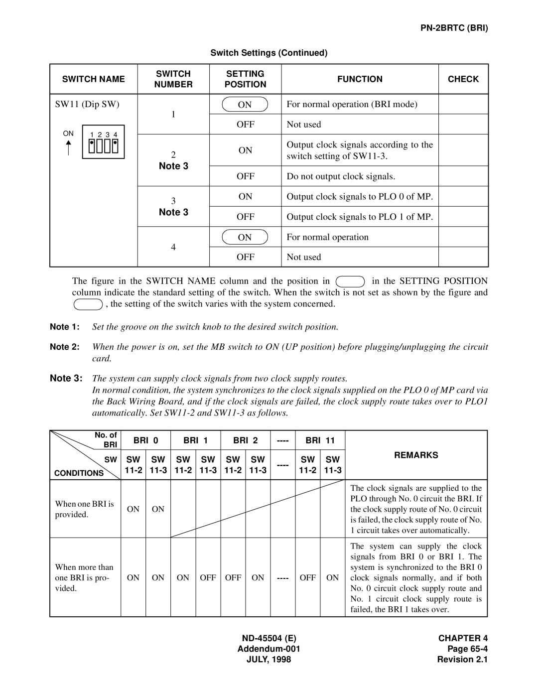
| Switch Settings (Continued) |
| ||
|
|
|
|
|
|
|
| |
SWITCH NAME | SWITCH | SETTING | FUNCTION | CHECK | ||||
NUMBER | POSITION | |||||||
|
|
|
|
|
| |||
|
|
|
|
|
|
|
| |
SW11 (Dip SW) | 1 | ON | For normal operation (BRI mode) |
| ||||
|
|
|
|
|
|
| ||
ON |
|
| OFF | Not used |
| |||
|
|
|
| |||||
1 2 3 4 |
|
|
| |||||
|
|
|
|
| ||||
2 | ON | Output clock signals according to the |
| |||||
|
|
|
|
| ||||
|
|
|
|
| ||||
|
|
|
| switch setting of |
| |||
|
|
|
|
|
| |||
|
|
|
|
|
| |||
|
|
|
| Note 3 |
|
|
| |
|
|
|
| OFF | Do not output clock signals. |
| ||
|
|
|
|
|
| |||
|
|
|
|
|
|
|
| |
|
|
|
| 3 | ON | Output clock signals to PLO 0 of MP. |
| |
|
|
|
|
|
|
| ||
|
|
|
| Note 3 | OFF | Output clock signals to PLO 1 of MP. |
| |
|
|
|
|
|
| |||
|
|
|
|
|
|
|
| |
|
|
|
| 4 | ON | For normal operation |
| |
|
|
|
|
|
|
| ||
|
|
|
| OFF | Not used |
| ||
|
|
|
|
|
| |||
|
|
|
|
|
|
|
| |
The figure in the SWITCH NAME column and the position in  in the SETTING POSITION column indicate the standard setting of the switch. When the switch is not set as shown by the figure and
  , the setting of the switch varies with the system concerned.
Note 1: Set the groove on the switch knob to the desired switch position.
Note 2: When the power is on, set the MB switch to ON (UP position) before plugging/unplugging the circuit card.
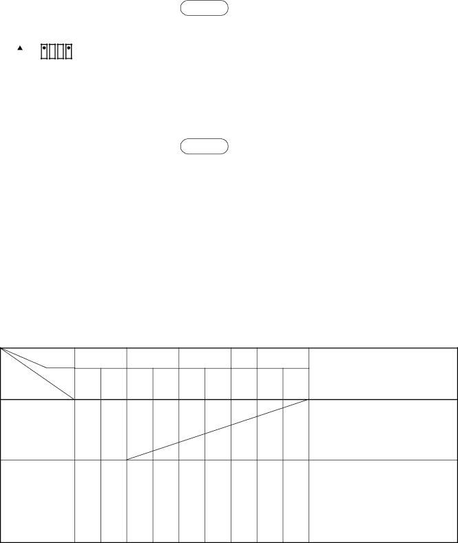
Note 3: The system can supply clock signals from two clock supply routes.
In normal condition, the system synchronizes to the clock signals supplied on the PLO 0 of MP card via the Back Wiring Board, and if the clock signals are failed, the clock supply route takes over to PLO1 automatically. Set
No. of | BRI 0 | BRI 1 | BRI 2 | BRI 11 |
| |||||
BRI |
| |||||||||
|
|
|
|
|
|
|
|
|
| |
SW | SW | SW | SW | SW | SW | SW | SW | SW | REMARKS | |
| ||||||||||
CONDITIONS |
|
|
| |||||||
|
| |||||||||
|
|
|
|
|
|
|
|
|
| |
|
|
|
|
|
|
|
|
|
| The clock signals are supplied to the |
When one BRI is |
|
|
|
|
|
|
|
|
| PLO through No. 0 circuit the BRI. If |
ON | ON |
|
|
|
|
|
|
| the clock supply route of No. 0 circuit | |
provided. |
|
|
|
|
|
|
| |||
|
|
|
|
|
|
|
|
| is failed, the clock supply route of No. | |
|
|
|
|
|
|
|
|
|
| |
|
|
|
|
|
|
|
|
|
| 1 circuit takes over automatically. |
|
|
|
|
|
|
|
|
|
| The system can supply the clock |
|
|
|
|
|
|
|
|
|
| signals from BRI 0 or BRI 1. The |
When more than |
|
|
|
|
|
|
|
|
| system is synchronized to the BRI 0 |
one BRI is pro- | ON | ON | ON | OFF | OFF | ON | OFF | ON | clock signals normally, and if both | |
vided. |
|
|
|
|
|
|
|
|
| No. 0 circuit clock supply route and |
|
|
|
|
|
|
|
|
|
| No. 1 circuit clock supply route is |
|
|
|
|
|
|
|
|
|
| failed, the BRI 1 takes over. |
|
|
|
|
|
|
|
| CHAPTER 4 | ||
|
|
|
|
|
| Page | ||||
|
|
|
|
|
| JULY, 1998 |
|
| Revision 2.1 | |