|
|
|
|
|
|
|
|
|
|
|
|
|
| ||
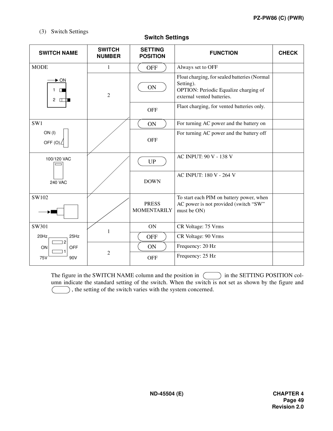
| (3) Switch Settings |
| Switch Settings |
| |||||||||||
|
|
|
|
|
|
|
|
|
|
|
|
|
| ||
|
|
|
|
|
|
|
|
|
|
|
|
|
|
|
|
| SWITCH NAME |
| SWITCH | SETTING | FUNCTION | CHECK | |||||||||
|
| NUMBER | POSITION | ||||||||||||
|
|
|
|
|
|
|
|
|
|
|
|
|
| ||
|
|
|
|
|
|
|
|
|
|
|
|
|
|
|
|
MODE |
|
|
|
| 1 | OFF | Always set to OFF |
| |||||||
|
|
|
|
|
|
|
|
|
|
|
|
|
|
|
|
|
|
|
| ON |
|
|
|
|
|
| Float charging, for sealed batteries (Normal |
| |||
|
|
|
|
|
|
|
|
| ON | Setting). |
| ||||
|
|
|
|
|
|
|
|
|
|
|
|
|
| ||
|
| 1 |
|
|
|
|
|
|
|
|
| OPTION: Periodic Equalize charging of |
| ||
|
|
|
|
|
|
|
|
|
| 2 |
|
| |||
|
| 2 |
|
|
|
|
|
|
|
|
| external vented batteries. |
| ||
|
|
|
|
|
|
|
|
|
|
|
|
|
| ||
|
|
|
|
|
|
|
|
|
|
|
|
|
|
|
|
|
|
|
|
|
|
|
|
|
|
|
|
| OFF | Flaot charging, for vented batteries only. |
|
|
|
|
|
|
|
|
|
|
|
|
|
|
| ||
|
|
|
|
|
|
|
|
|
|
|
|
|
|
| |
|
|
|
|
|
|
|
|
|
|
|
|
|
|
|
|
SW1 |
|
|
|
|
| ON | For turning AC power and the battery on |
| |||||||
|
|
|
|
|
|
|
|
|
|
|
|
|
|
|
|
| ON (I) |
|
|
|
|
|
|
| For turning AC power and the battery off |
| |||||
| OFF (O) |
|
|
|
|
|
|
| OFF |
|
| ||||
|
|
|
|
|
|
|
|
|
| ||||||
|
|
|
|
|
|
|
|
|
|
|
|
|
|
|
|
|
|
|
|
|
|
|
|
|
|
|
|
|
|
|
|
| 100/120 VAC |
|
| UP | AC INPUT: 90 V - 138 V |
| |||||||||
|
|
|
|
| |||||||||||
|
|
|
|
|
|
|
|
|
|
|
|
|
|
| |
|
|
|
|
|
|
|
|
|
|
|
|
|
|
| |
|
|
|
|
|
|
|
|
|
|
|
|
|
|
|
|
|
|
|
|
|
|
|
|
|
|
|
|
|
| AC INPUT: 180 V - 264 V |
|
|
|
|
|
|
|
|
|
|
|
| DOWN |
|
| ||
|
|
| 240 VAC |
|
|
|
|
|
|
| |||||
|
|
|
|
|
|
|
|
|
|
|
|
|
|
|
|
SW102 |
|
|
|
|
|
| To start each PIM on battery power, when |
| |||||||
|
|
|
|
|
|
|
|
|
|
|
|
| PRESS | AC power is not provided (switch “SW” |
|
|
|
|
|
|
|
|
|
|
|
|
|
|
| ||
|
|
|
|
|
|
|
|
|
|
|
|
| MOMENTARILY | must be ON) |
|
|
|
|
|
|
|
|
|
|
|
|
|
|
| ||
|
|
|
|
|
|
|
|
|
|
|
|
|
| ||
|
|
|
|
|
|
|
|
|
|
|
|
|
|
|
|
|
|
|
|
|
|
|
|
|
|
|
|
|
|
|
|
|
|
|
|
|
|
|
|
|
|
|
|
|
|
|
|
SW301 |
|
|
|
| 1 | ON | CR Voltage: 75 Vrms |
| |||||||
|
|
|
|
|
|
|
|
|
|
|
|
|
|
| |
20Hz |
|
|
|
|
| 25Hz |
| OFF | CR Voltage: 90 Vrms |
| |||||
|
|
|
|
|
| ||||||||||
|
|
| 2 |
| OFF |
|
| ON | Frequency: 20 Hz |
| |||||
| ON |
|
|
| 1 |
|
| 2 |
| ||||||
|
|
|
|
|
|
|
|
|
|
| |||||
|
|
|
| OFF | Frequency: 25 Hz |
| |||||||||
|
|
|
|
|
|
|
|
|
|
|
| ||||
| 75V | 90V |
|
|
| ||||||||||
|
|
|
|
| |||||||||||
|
|
|
|
|
|
|
|
|
|
|
|
|
|
|
|
The figure in the SWITCH NAME column and the position in  in the SETTING POSITION col- umn indicate the standard setting of the switch. When the switch is not set as shown by the figure and
  , the setting of the switch varies with the system concerned.
Page 49
Revision 2.0