PN-CP03/PN-CP03-C (MP)
Switch Settings (Continued)
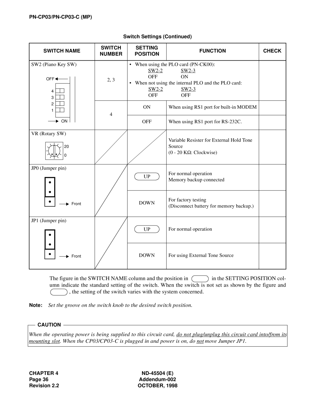
SWITCH NAME | SWITCH | SETTING | FUNCTION | CHECK | ||||||||||
NUMBER | POSITION | |||||||||||||
|
|
|
|
|
|
|
|
|
|
|
| |||
|
|
|
|
|
|
|
|
|
|
|
|
|
| |
SW2 (Piano Key SW) |
| • When using the PLO card |
| |||||||||||
|
|
|
|
|
|
|
|
|
|
|
| |||
OFF |
|
|
|
|
|
|
| 2, 3 | OFF | ON |
| |||
|
|
|
|
|
|
|
| |||||||
|
|
|
|
|
|
|
| |||||||
|
|
|
|
| • When not using the internal PLO and the PLO card: |
| ||||||||
|
|
|
|
|
|
|
|
|
|
|
| |||
|
|
|
|
|
|
|
|
|
|
|
| |||
4 |
|
|
|
|
|
|
|
|
|
| ||||
|
|
|
|
|
|
|
|
|
| |||||
|
|
|
|
|
|
|
|
| OFF | OFF |
| |||
3 |
|
|
|
|
|
|
|
|
|
| ||||
|
|
|
|
|
|
|
|
|
| |||||
|
|
|
|
|
|
|
|
|
|
|
| |||
2 |
|
|
|
|
|
|
|
|
|
|
|
| ||
|
|
|
|
|
|
|
|
| ON | When using RS1 port for |
| |||
|
|
|
|
|
|
|
|
|
| |||||
1 |
|
|
|
|
|
|
|
| 4 |
| ||||
|
|
|
|
|
|
|
|
|
|
| ||||
|
|
|
|
|
|
|
|
|
|
|
|
| ||
|
|
|
|
|
|
|
|
|
| OFF | When using RS1 port for |
| ||
|
|
|
| ON |
|
|
|
|
| |||||
|
|
|
| |||||||||||
|
|
|
|
|
|
|
|
| ||||||
|
|
|
|
|
|
|
|
|
|
|
|
|
| |
VR (Rotary SW) |
|
|
|
| Variable Resister for External Hold Tone |
20 |
| Source |
0 |
| (0 - 20 KΩ: Clockwise) |
|
| |
JP0 (Jumper pin) |
| For normal operation |
| UP | |
| Memory backup connected | |
|
|
|
|
|
| Front | DOWN | For factory testing |
|
|
|
| (Disconnect battery for memory backup.) | ||
|
|
|
| |||
|
|
|
|
|
| |
|
|
|
|
|
|
|
JP1 (Jumper pin) |
|
| ||||
|
|
|
|
| UP | For normal operation |
|
|
|
|
|
|
|
Front
DOWN
For using External Tone Source
The figure in the SWITCH NAME column and the position in  in the SETTING POSITION col- umn indicate the standard setting of the switch. When the switch is not set as shown by the figure and
  , the setting of the switch varies with the system concerned.
Note: Set the groove on the switch knob to the desired switch position.
CAUTION
When the operating power is being supplied to this circuit card, do not plug/unplug this circuit card into/from its mounting slot. When the
CHAPTER 4 | |
Page 36 | |
Revision 2.2 | OCTOBER, 1998 |