| Table | ||
|
|
| |
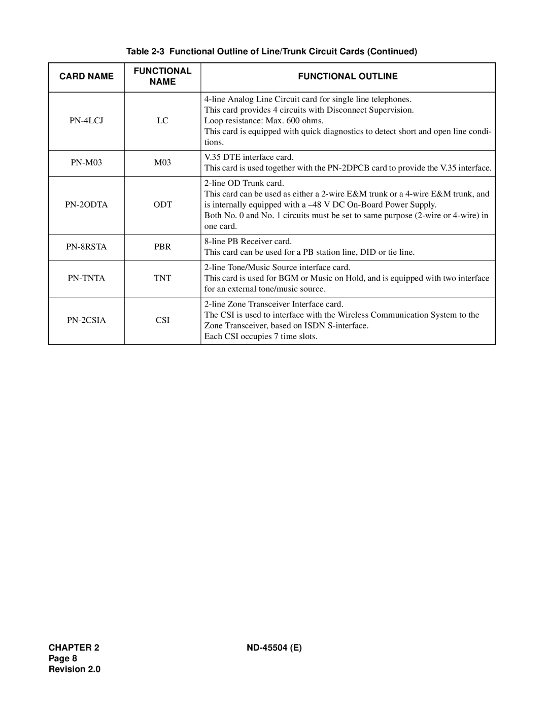
CARD NAME | FUNCTIONAL | FUNCTIONAL OUTLINE | |
NAME | |||
|
| ||
|
|
| |
|
| ||
|
| This card provides 4 circuits with Disconnect Supervision. | |
| LC | Loop resistance: Max. 600 ohms. | |
|
| This card is equipped with quick diagnostics to detect short and open line condi- | |
|
| tions. | |
|
|
| |
M03 | V.35 DTE interface card. | ||
This card is used together with the | |||
|
| ||
|
|
| |
|
| ||
|
| This card can be used as either a | |
| ODT | is internally equipped with a | |
|
| Both No. 0 and No. 1 circuits must be set to same purpose | |
|
| one card. | |
|
|
| |
| PBR | ||
This card can be used for a PB station line, DID or tie line. | |||
|
| ||
|
|
| |
|
| ||
| TNT | This card is used for BGM or Music on Hold, and is equipped with two interface | |
|
| for an external tone/music source. | |
|
|
| |
|
| ||
| CSI | The CSI is used to interface with the Wireless Communication System to the | |
Zone Transceiver, based on ISDN | |||
|
| ||
|
| Each CSI occupies 7 time slots. | |
|
|
| |
CHAPTER 2 |
Page 8
Revision 2.0