CHAPTER 3 CIRCUIT CARD INSTALLATION CONDITIONS
This chapter explains the conditions for installing various kinds of circuit cards used in the PBX.
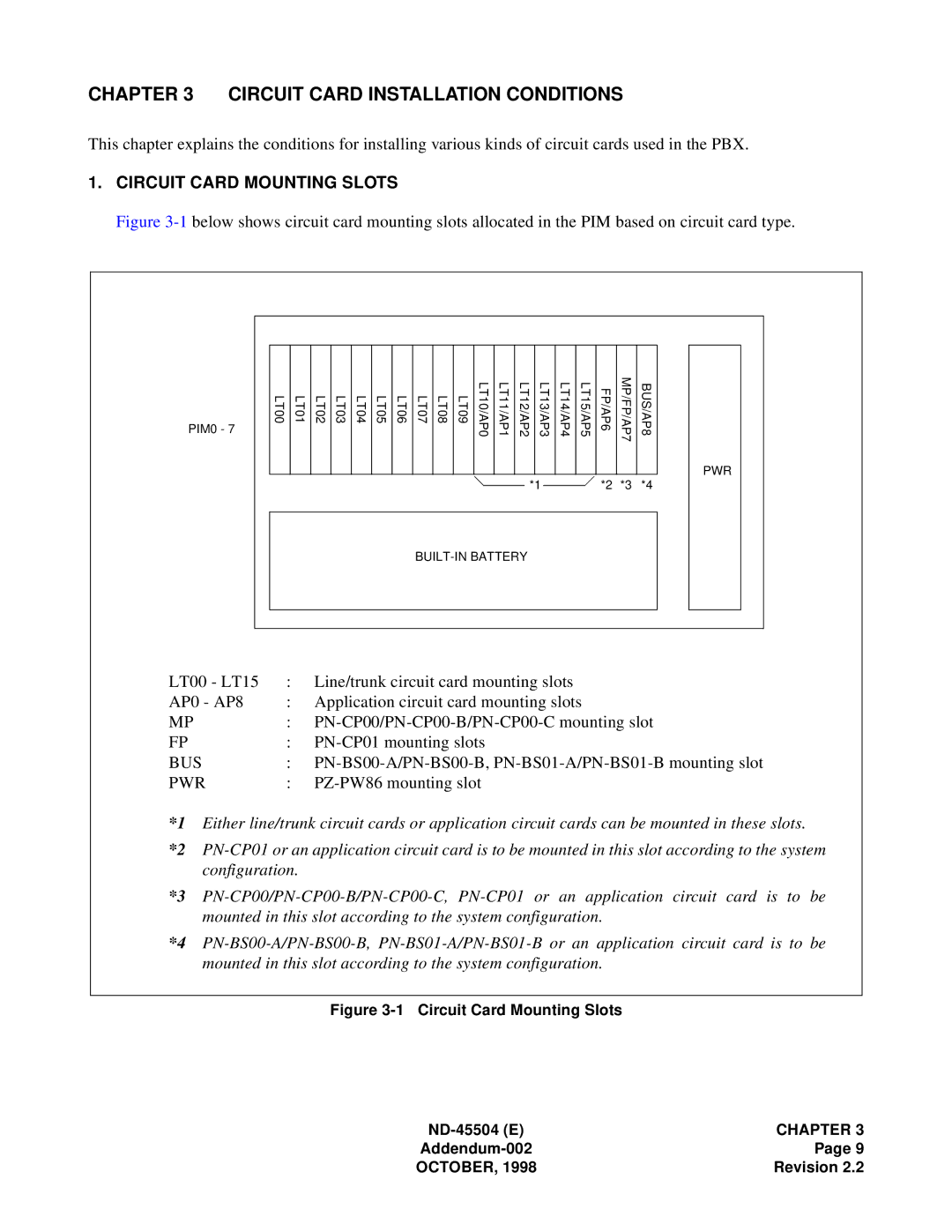
1.CIRCUIT CARD MOUNTING SLOTS
Figure 3-1 below shows circuit card mounting slots allocated in the PIM based on circuit card type.
PIM0 - 7 | LT01 | LT02 | LT03 | LT04 | LT05 | LT06 | LT07 | LT08 | LT09 | LT10/AP0 | LT11/AP1 | LT12/AP2 | LT13/AP3 | LT14/AP4 | LT15/AP5 | FP/AP6 | MP/FP/AP7 | BUS/AP8 |
LT00 | ||||||||||||||||||
|
|
|
|
|
|
|
|
|
|
|
|
|
|
|
|
|
| PWR |
|
|
|
|
|
|
|
|
|
|
|
|
| *1 |
|
| *2 | *3 | *4 |
|
|
|
|
|
|
|
|
|
|
|
|
| ||||||
LT00 - LT15 | : Line/trunk circuit card mounting slots | |
AP0 - AP8 | : Application circuit card mounting slots | |
MP | : | |
FP | : | |
BUS | : | |
PWR | : | |
*1 Either line/trunk circuit cards or application circuit cards can be mounted in these slots.
*2
*3
*4
Figure 3-1 Circuit Card Mounting Slots
| CHAPTER 3 |
Page 9 | |
OCTOBER, 1998 | Revision 2.2 |