PAGE No. |
|
|
| ADD. No. |
|
|
|
| PAGE No. |
|
|
|
| ADD. No. |
|
|
| |||||||
|
|
|
|
|
|
|
|
|
|
|
|
|
|
|
|
|
|
|
|
| ||||
001 | 002 | 003 | 004 |
| 005 | 006 | 007 | 008 |
| 001 | 002 | 003 |
| 004 | 005 | 006 | 007 | 008 | ||||||
|
|
|
|
|
|
| ||||||||||||||||||
i |
| 2.2 |
|
|
|
|
|
|
|
|
| 35 |
|
| 2.2 |
|
|
|
|
|
|
|
| |
ii | 2.1 |
|
|
|
|
|
|
|
|
|
| 36 |
|
| 2.2 |
|
|
|
|
|
|
|
| |
iii |
|
|
|
|
|
|
|
|
|
|
| 37 |
|
|
|
|
|
|
|
|
|
|
| |
iv |
|
|
|
|
|
|
|
|
|
|
| 38 |
|
|
|
|
|
|
|
|
|
|
| |
1 |
|
|
|
|
|
|
|
|
|
|
|
| 39 |
|
| 2.2 |
|
|
|
|
|
|
|
|
2 |
|
|
|
|
|
|
|
|
|
|
|
| 40 |
| 2.1 | 2.2 |
|
|
|
|
|
|
|
|
3 |
|
| 2.2 |
|
|
|
|
|
|
|
|
| 41 |
|
| 2.2 |
|
|
|
|
|
|
|
|
4 |
| 2.1 |
|
|
|
|
|
|
|
|
|
| 42 |
|
|
|
|
|
|
|
|
|
|
|
5 |
| 2.1 |
|
|
|
|
|
|
|
|
|
| 43 |
|
|
|
|
|
|
|
|
|
|
|
6 |
|
|
|
|
|
|
|
|
|
|
|
| 44 |
|
|
|
|
|
|
|
|
|
|
|
7 |
|
|
|
|
|
|
|
|
|
|
|
| 45 |
|
|
|
|
|
|
|
|
|
|
|
8 |
|
|
|
|
|
|
|
|
|
|
|
| 46 |
|
|
|
|
|
|
|
|
|
|
|
9 |
|
| 2.2 |
|
|
|
|
|
|
|
|
| 47 |
|
|
|
|
|
|
|
|
|
|
|
10 |
|
| 2.2 |
|
|
|
|
|
|
|
|
| 48 |
|
|
|
|
|
|
|
|
|
|
|
11 |
|
| 2.2 |
|
|
|
|
|
|
|
|
| 49 |
|
|
|
|
|
|
|
|
|
|
|
12 |
|
| 2.2 |
|
|
|
|
|
|
|
|
| 50 |
|
|
|
|
|
|
|
|
|
|
|
13 |
|
|
|
|
|
|
|
|
|
|
|
| 51 |
|
|
|
|
|
|
|
|
|
|
|
14 |
| 2.1 |
|
|
|
|
|
|
|
|
|
| 52 |
| 2.1 |
|
|
|
|
|
|
|
|
|
15 |
|
|
|
|
|
|
|
|
|
|
|
| 53 |
|
|
|
|
|
|
|
|
|
|
|
16 |
|
|
|
|
|
|
|
|
|
|
|
| 54 |
|
|
|
|
|
|
|
|
|
|
|
17 |
|
|
|
|
|
|
|
|
|
|
|
| 55 |
|
|
|
|
|
|
|
|
|
|
|
18 |
|
|
|
|
|
|
|
|
|
|
|
| 56 |
|
|
|
|
|
|
|
|
|
|
|
19 |
|
|
|
|
|
|
|
|
|
|
|
| 57 |
|
|
|
|
|
|
|
|
|
|
|
20 |
|
|
|
|
|
|
|
|
|
|
|
| 58 |
|
|
|
|
|
|
|
|
|
|
|
21 |
|
| 2.2 |
|
|
|
|
|
|
|
|
| 59 |
|
|
|
|
|
|
|
|
|
|
|
22 |
|
|
|
|
|
|
|
|
|
|
|
| 60 |
|
|
|
|
|
|
|
|
|
|
|
23 |
|
|
|
|
|
|
|
|
|
|
|
| 61 |
|
|
|
|
|
|
|
|
|
|
|
24 |
|
|
|
|
|
|
|
|
|
|
|
| 62 |
|
|
|
|
|
|
|
|
|
|
|
25 |
|
|
|
|
|
|
|
|
|
|
|
| 63 |
|
|
|
|
|
|
|
|
|
|
|
26 |
|
|
|
|
|
|
|
|
|
|
|
| 64 |
|
|
|
|
|
|
|
|
|
|
|
27 |
|
|
|
|
|
|
|
|
|
|
|
| 65 |
|
|
|
|
|
|
|
|
|
|
|
28 |
|
|
|
|
|
|
|
|
|
|
|
| 2.1 |
|
|
|
|
|
|
|
|
| ||
29 |
| 2.1 |
|
|
|
|
|
|
|
|
|
| 2.1 |
|
|
|
|
|
|
|
|
| ||
30 |
|
|
|
|
|
|
|
|
|
|
|
| 2.1 |
|
|
|
|
|
|
|
|
| ||
31 |
|
| 2.2 |
|
|
|
|
|
|
|
|
| 2.1 |
|
|
|
|
|
|
|
|
| ||
32 |
| 2.1 | 2.2 |
|
|
|
|
|
|
|
|
| 66 |
|
|
|
|
|
|
|
|
|
|
|
33 |
|
| 2.2 |
|
|
|
|
|
|
|
|
| 67 |
| 2.1 |
|
|
|
|
|
|
|
|
|
34 |
|
| 2.2 |
|
|
|
|
|
|
|
|
| 68 |
|
|
|
|
|
|
|
|
|
|
|
|
|
|
|
|
|
|
|
|
|
|
|
| ||||||||||||
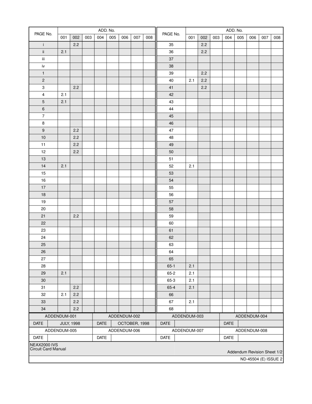
DATE |
| JULY, 1998 |
| DATE |
|
| OCTOBER, 1998 |
| DATE |
|
|
|
|
| DATE |
|
|
|
|
| ||||
|
|
|
|
|
|
|
|
| ||||||||||||||||
|
|
|
|
|
|
|
|
|
|
|
|
|
|
|
|
|
|
|
|
|
|
| ||
DATE |
|
|
|
| DATE |
|
|
|
|
|
| DATE |
|
|
|
|
| DATE |
|
|
|
|
| |
|
|
|
|
|
|
|
|
|
|
|
|
|
|
|
|
|
|
|
|
|
|
|
|
|
NEAX2000 IVS
Circuit Card Manual
Addendum Revision Sheet 1/2