Note 1: Set the groove on the switch knob to the desired switch position.
Note 2: When the power is on, flip the MB switch to ON (UP position) before plugging/unplugging the circuit card.
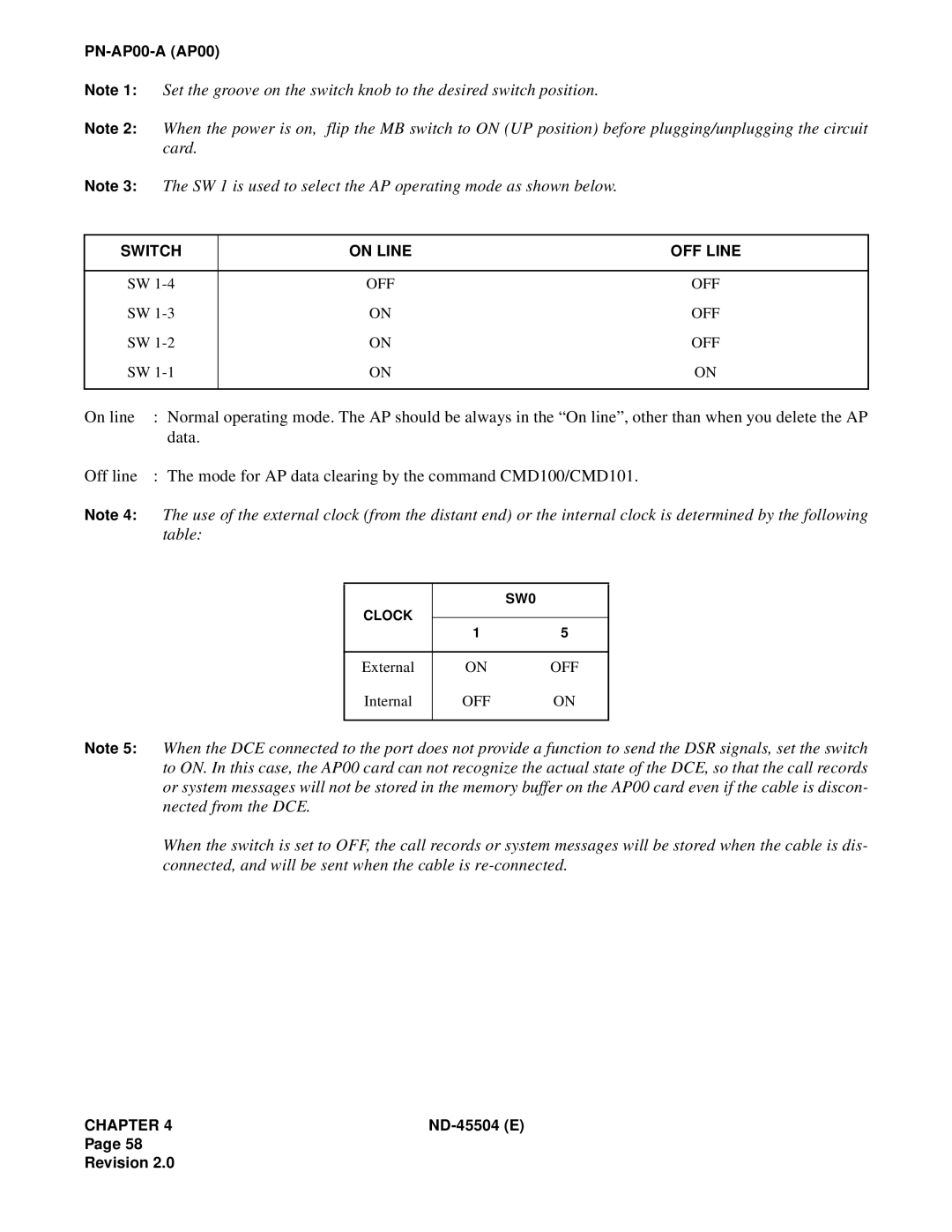
Note 3: The SW 1 is used to select the AP operating mode as shown below.
SWITCH | ON LINE | OFF LINE |
|
|
|
SW | OFF | OFF |
SW | ON | OFF |
SW | ON | OFF |
SW | ON | ON |
|
|
|
On line | : Normal operating mode. The AP should be always in the “On line”, other than when you delete the AP | ||||
| data. |
|
|
| |
Off line | : The mode for AP data clearing by the command CMD100/CMD101. | ||||
Note 4: | The use of the external clock (from the distant end) or the internal clock is determined by the following | ||||
| table: |
|
|
| |
|
|
|
|
|
|
|
|
|
| SW0 |
|
|
| CLOCK |
|
|
|
|
| 1 | 5 |
| |
|
|
|
| ||
|
|
|
|
|
|
|
| External | ON | OFF |
|
|
| Internal | OFF | ON |
|
|
|
|
|
| |
Note 5: | When the DCE connected to the port does not provide a function to send the DSR signals, set the switch | ||||
| to ON. In this case, the AP00 card can not recognize the actual state of the DCE, so that the call records | ||||
| or system messages will not be stored in the memory buffer on the AP00 card even if the cable is discon- | ||||
| nected from the DCE. |
|
|
| |
When the switch is set to OFF, the call records or system messages will be stored when the cable is dis- connected, and will be sent when the cable is
CHAPTER 4 |
Page 58
Revision 2.0
