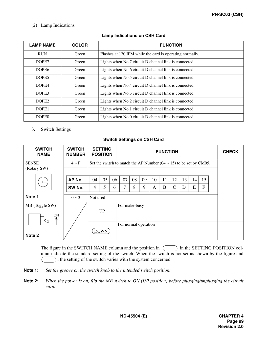
(2) Lamp Indications
|
| Lamp Indications on CSH Card |
|
|
|
LAMP NAME | COLOR | FUNCTION |
|
|
|
RUN | Green | Flashes at 120 IPM while the card is operating normally. |
|
|
|
DOPE7 | Green | Lights when No.7 circuit D channel link is connected. |
|
|
|
DOPE6 | Green | Lights when No.6 circuit D channel link is connected. |
|
|
|
DOPE5 | Green | Lights when No.5 circuit D channel link is connected. |
|
|
|
DOPE4 | Green | Lights when No.4 circuit D channel link is connected. |
|
|
|
DOPE3 | Green | Lights when No.3 circuit D channel link is connected. |
|
|
|
DOPE2 | Green | Lights when No.2 circuit D channel link is connected. |
|
|
|
DOPE1 | Green | Lights when No.1 circuit D channel link is connected. |
|
|
|
DOPE0 | Green | Lights when No.0 circuit D channel link is connected. |
|
|
|
3.Switch Settings
Switch Settings on CSH Card
SWITCH |
| SWITCH |
| SETTING |
|
|
|
|
| FUNCTION |
|
|
|
| CHECK | |||||||||
| NAME |
| NUMBER |
| POSITION |
|
|
|
|
|
|
|
| |||||||||||
|
|
|
|
|
|
|
|
|
|
|
|
|
|
| ||||||||||
|
|
|
|
|
|
|
|
|
|
|
|
|
|
|
|
|
|
|
|
|
|
|
| |
SENSE |
| 4 ~ F | Set the switch to match the AP Number (04 ~ 15) to be set by CM05. | |||||||||||||||||||||
(Rotary SW) |
|
|
|
|
|
|
|
|
|
|
|
|
|
|
|
|
|
|
| |||||
|
|
|
|
|
|
|
|
|
|
|
|
|
|
|
|
|
|
| ||||||
|
|
|
|
|
|
|
|
|
|
|
|
|
|
|
|
|
|
|
|
|
|
|
| |
|
|
|
|
|
|
|
|
|
|
|
|
|
|
|
|
|
|
|
|
|
|
|
| |
|
|
|
|
|
|
| AP No. |
| 04 | 05 |
| 06 | 07 | 08 | 09 | 10 | 11 | 12 | 13 | 14 | 15 |
|
| |
|
|
|
|
|
|
|
|
|
|
|
|
|
|
|
|
|
|
|
|
|
|
|
| |
|
|
|
|
|
|
| SW No. |
| 4 | 5 |
| 6 |
| 7 | 8 | 9 | A | B | C | D | E | F |
|
|
|
|
|
|
|
|
|
|
|
|
|
|
|
|
|
|
|
|
|
|
|
|
|
|
|
Note 1 | 0 ~ 3 | Not used |
MB (Toggle SW) |
| For |
ON |
| UP |
|
| |
|
| For normal operation |
Note 2 |
| DOWN |
|
|
The figure in the SWITCH NAME column and the position in  in the SETTING POSITION col- umn indicate the standard setting of the switch. When the switch is not set as shown by the figure and
  , the setting of the switch varies with the system concerned.
Note 1: Set the groove on the switch knob to the intended switch position.
Note 2: When the power is on, flip the MB switch to ON (UP position) before plugging/unplugging the circuit card.
CHAPTER 4 |
Page 99
Revision 2.0