ASMi-52
Page
ASMi-52
Limited Warranty
Please observe the following precautions
General Safety Instructions
Connection of DC Mains
General Safety Practices
Connection of AC Mains
TNV-2
Ports Safety Status
TNV-3
Isdn
Electromagnetic Compatibility EMC
Canadian Emission Requirements
Supplementary Information
Safety
Configuring ASMi-52
Installing ASMi-52
Connecting the Interfaces
Connecting the Power
Configuring the Shdsl Interface
Configuring the Master Clock
Configuring the DTE Interface
Configuring the Serial Interface
Configuring the 10/100BaseT Interface
Configuring the T1 Interface
To configure E1 parameters
To configure the T1 parameters
Quick Start Guide Configuring ASMi-52 ASMi-52 Ver
Contents
Troubleshooting and Diagnostics
Configuring a Typical Application
Versions
Overview
DTE Interface
Line Interface
Unit Enclosure
Applications
ASMi-52 Modems Operating opposite ASMi-52CD Cards
Data Rate Wire
Features
Functionality
Typical Ranges 26 AWG
DTE Interface
Sum for all the interfaces
ASMi-52 Data Rates Low Speed Mode
ASMi-52 Data Rates
DTE+LAN
Multiplexer Applications
Serial DTE = V.35, X.21, RS-530, IR-IP
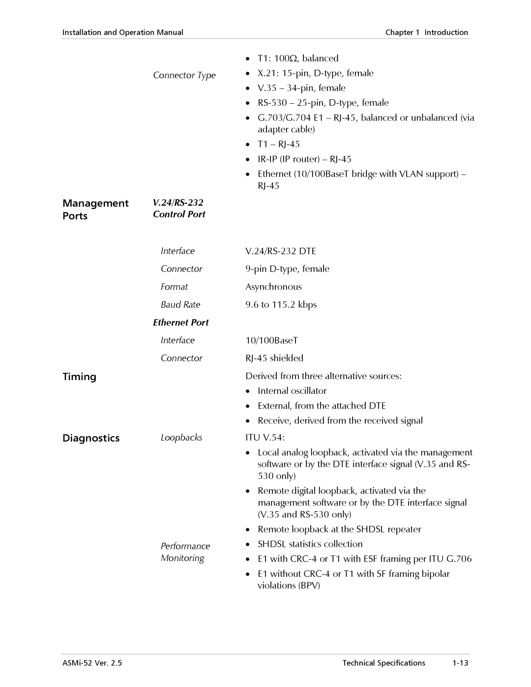
Timing
Management
Diagnostics
Physical Description
Alarm Reporting
Functional Description
Statistics Collection
ASMi-52 modem consists of the following major modules
Technical Specifications
Diagnostics Loopbacks
Power Consumption
PWR green Power Test red
Synchronization of DSL line
Height
Environment
Introduction Technical Specifications ASMi-52 Ver
Site Requirements and Prerequisites
To install ASMi-52
Introduction
Connecting the Interface Cables
Package Contents
Connecting the Line
Connecting the Power Cables
Connecting the DTE Interface
Connecting the Alarm Relay Connector
Connecting DC Power
Connecting AC Power
To connect AC power
To connect DC power
To turn on ASMi-52
Controls and Indicators
Turning On ASMi-52
ASMi-52 Front Panel, E1 Interface 2 Wire
Normal Indications
ASMi-52 Indicator Status
ASMi-52 Front Panel LEDs
ASMi-52 Rear Panel LEDs
Default Settings
Default Settings
Parameter Default Value System
LAN Configuration
DCE
Parameter Default Value Control Port
CTS =RTS DSR
OFF
Parameter Default Value Serial DTE Interface
Configuration Alternatives
E1/E1+Ethernet/E1+Serial DTE Interface
T1 Interface
Managing ASMi-52 via a Terminal Port
Control Port Interface Characteristics
Preparing the Terminal
Data Terminal Ready DTR
Correcting Entries
Navigating the Management Menus
Navigating Data Forms
To choose an option
Managing ASMi-52 via Ethernet Port
To start the ConfiguRAD session
Managing ASMi-52 via a Dedicated Timeslot
To prepare ASMi-52 for network management
Managing ASMi-52 via LAN Port and a Dedicated Timeslot
Managing ASMi-52 via Web Browser
Configuration Menus
10. Inventory and Configuration Menus
11. Monitoring, Diagnostics and File Utilities Menus
Logging Out
Turning Off ASMi-52
To end the current session
To turn off ASMi-52
Configuring Management Parameters
Configuring ASMi-52 for Management
To access the Management menu
MTU means Maximum Transfer Unit
To enter device information
Entering Device Information
To clear system parameters
Type Y to confirm the deletion
Configuring the Network Managers
Configuring the Host Parameters
To configure the network managers
To define the IP parameters
To define the management access method
Controlling the Management Access
To configure dedicated timeslots
Configuring Dedicated Timeslots
To enable Vlan mode
Configuring Vlan Encapsulation
With autonegotiation enabled
Configuring the LAN Port
Configuring the LAN Port Operation Mode
To remove a MAC address from the table
Filling out the Bridging Table
To fill out the bridge table
Configuring QoS Mapping
Configuring Aging Timeout
To configure aging timeout
To configure Vlan Priority QoS Mapping
To set the LAN rate
Setting the LAN Rate
Information to be transmitted to the DSL line
To set autonegotiation
Setting the LAN Rate in a Multiplexer Unit
Configuring Autonegotiation
Configuring Fault Indication
Configuring ASMi-52 System Parameters
To set the fault indication
To access the Configuration menu
To display the System Configuration menu
16. Configuration Menu
To configure local card mode
Configuring Local Card Mode
Configuring Low Speed Operation
Configuring Remote Card Mode
To configure remote card mode
To enable the low speed operation
To access the Control port menu
Configuring Control Port Parameters
To configure the control port data rate
Changing the Control Port Data Rate
Selecting the Control Port Interface
Configuring the Terminal Port
Selecting the CTS State
Selecting the DSR State
To access the Terminal menu
Configuring the Port Control Mode
Currently, the connection to ASMi-52 via Slip is disabled
To enable or disable the pop-up alarms
To change the user name and password
To change the dial-out parameters
To configure the security timeout
To set the G.704 interface type
Setting the G.704 Interface Type
To change the transmission mode
Configuring the Physical Ports
Configuring the Snext Margin
Configuring the Power Backoff
To configure the use of the power backoff
To configure the Snext margin
To configure the current margin
Configuring the Current Margin
Setting the Loop Attenuation Threshold
Configuring the Power Spectral Density
Configuring Line Probing
Configuring the Shdsl Repeater
Setting the SNR Margin Threshold
To access the Shdsl Repeater menu
To set the SNR margin threshold
To select the data rate
Configuring the DTE Interface Data Rate
Configuring the Data Rate in a Multiplexer Unit
To access the E1 Port Configuration menu
Configuring the E1 Interface
To select E1 framing mode
Selecting E1 Framing Mode
To enable CRC-4 code generation
Setting the Sync Mode
Enabling CRC-4 Code Generation
To select resynchronization time
Mapping E1 Timeslots
Defining Idle Code
To define an idle code
To assign E1 timeslots
Opposite remote units with a serial data interface
You can configure timeslot 0 to be looped or transparent
Mapping E1 Timeslots in a Multiplexer Unit
To map E1 timeslots in a multiplexer unit with E1 + LAN
Matching Remote Unit Settings With Local Unit Settings
To match remote unit settings with local unit settings
Configuring the T1 Interface
37. T1 Port Configuration
To access the T1 Configuration menu
Additional Tasks
To access the Monitoring menu
Displaying the ASMi-52 Status
Displaying the System Status
To display the port status information
Alarms are described in Chapter
Displaying the Port Status
Accessing the Remote ASMi-52
Entering the User Name and Password
To access the remote ASMi-52
To close a virtual terminal
Type in your user name and press Tab
Type in your password at the prompt up to eight characters
ASMi-52 responds to your entry with asterisks
Press Enter
To display the ASMi-52 inventory
Displaying the ASMi-52 Inventory
Updating Software Releases
Installing a New Software Release via Tftp
To install a new software release via Tftp
Port Data Rate section above
Displaying the following message
To upload a configuration from the source device
Autoconfiguration through Tftp or Xmodem
During the software installation, the TST indicator blinks
To display the software version
To download a configuration file to the target devices
Displaying the Software Version
To swap software versions
Resetting ASMi-52
Switching the Software Versions
Resetting the ASMi-52 Modem
Resetting to Default Settings
To reset ASMi-52 to the factory default
Units equipped with the management LAN port
To reset the line interface of the Shdsl repeater
Resetting the Shdsl Repeater
Exiting the Control Session
52. Repeater Reset Menu
Application
Guidelines for Configuring ASMi-52 Units
Setting the ASMi-52 System Parameters
Configuring the ASMi-52 units
To enter the user name and password
To prepare a control session
To set the device host IP address
Setting the E1 Port
Configuring the Serial DTE Interface
Configuring the Line Interface Type
Configuring LLB/RLB Activation from DTE
To configure the line interface type for ASMi-52 units
DTE Local Port Menu
Page
Displaying Shdsl Statistics
Monitoring Performance
Displaying the Current Shdsl Statistics
To display the current Shdsl statistics
Shdsl Port Performances Menu
Shdsl Statistics Parameters
Displaying the Shdsl Statistics for all Intervals
To display the Shdsl statistics fo r all intervals
Display Description
CRC-4 Disabled E1, SF framing T1
CRC-4 Enabled E1, ESF framing T1
Displaying E1/T1 Statistics
Clearing the Shdsl Performance Statistics
To display the current E1/T1 statistics
Displaying the Current E1/T1 Statistics
Chapter
Display Description Range
Displaying E1/T1 Statistics for All Intervals
Timer
E1 Statistics Parameters
To display E1/T1 statistics for all intervals
Handling Alarms
Detecting Errors
Power-Up Self-Test
Front Panel LEDs
To display all alarms
Displaying All Alarms
Displaying the Port Status
Working with the System Log File
To display the system log file
To clear the system log file
To mask ASMi-52 alarms
Masking Port Alarms
ASMi-52 Alarms and Warnings
Number Terminal Message Port Description Severity
T1-TS not Rate Comp E1 Signal Loss DTE
CRC Error Over Shdsl
T1 Signal Loss E1 BPV ERR EXC DTE
Losw Failure Over Shdsl
Excesive ERR DTE
Wire Mode not Shdsl
Ratio T1 Excesive ERR AIS Occured DTE
T1 AIS Occured AIS and Sync DTE
Line Paramers not Shdsl
Customer Side
External to DTE
Internal Clock
Working with the Port Log File
Troubleshooting
ASMi-52 Events
To display the log file
To clear the log file
Testing ASMi-52
Bert Patterns
Bit Error Rate Test Bert
16. Bert Menu
To configure the Bert results
Loopback in Multiplexer Units
Running Loopback Tests
20. Loopback with Multiplexer Units
Running the Local Loopback
To run the local loopback
22. Diagnostics Menu
To activate the remote loopback
Running the Remote Loopback
Running Remote Loopback at a Repeater
To deactivate a running loopback
Deactivating the Loopbacks
To activate the remote loopback at the Shdsl repeater
Running the LEDs Test
Frequently Asked Questions
To deactivate multiple loopbacks
To run the LEDs test
Technical Support
Page
Table A-1. V.35, X.21 and RS-530 Connector Pinouts
DTE Interface Connectors
35, X.21 and RS-530 Interface Connectors
Description Function 34-Pin DB-25 DB-15 Circuit
35, X.21 and RS-530 Connector Pinouts
Ethernet Connector
E1 and T1 Interface Connector
Table A-4. Control Connector Pinout
Control Connector
Table A-5. Control Connector Signal Direction
Cross cable with two male DB-9 connectors
DB-9 Pin
Alarm Relay Connector
Table A-6. Cross Cable Pinout
Page
Overview
Appendix B IR-IP Interface Module
Operation Mode Full duplex or half duplex user-selectable
RJ-45 shielded 8-pin connector
Standard Conforms to Ieee Data Rate
Interface Type
Table B-2. IR-IP DIP Switch Functions
IR-IP DIP Switch
Table B-1 RJ-45 Pinout
This appendix
Power-Up Indications for Configured IP Router Card
Power-Up Indications for Unconfigured IP Router Card
Indications during Normal Service
Table B-3. IR-IP Interface Indicators
IR-IP Management Subsystem
Accessing the IR-IP Management Subsystem
Default IP Communication Parameters
Performing Preliminary Configuration
Outline of Preliminary Configuration
To perform the preliminary configuration procedure
Preliminary Telnet Host Configuration
Connecting the Telnet Host
Assigning the Router LAN Interface Address
IP Learning Mechanism
Assigning a LAN IP Address to a New IR-IP
To view and edit the ARP table contents
To configure the IP router LAN address
Changing the LAN IP Address of a Configured IR-IP
General Operating Procedures
Documentation to find how to select a proper font
IR-IP Management Utility
Menu Structure of Management Utility
Starting a Management Utility
To perform quick setup
Quick Setup Guide
Operation without Default Gateway
Default Gateway
Operation with Default Gateway
Parameters
Figure B-7. Selecting the IP Subnet Mask
Reading Protocol from DIP Switches
Defining a Telnet Password
Defining Management Access
Setting Telnet Inactivity Timeout
To access the Management Access menu
Defining the Interface Parameters
Advanced Setup
Defining the Device Identification
Figure B-10. Interface Parameters Menu
To define the Frame Relay protocol parameters
Defining the WAN Protocol Parameters
Frame Relay Protocol
To define the PPP Protocol Parameters
PPP Protocol Menu
To define the Multicast Parameters
Defining the Multicast Parameters
To access the Device Control menu
Using the Device Control Menu
To access the Static Groups menu
To download new software
Viewing the Error Log
Downloading New Software
Resetting IR-IP
Erasing Configuration
Reset LAN
To reset the LAN interface
Reset WAN
Viewing IR-IP configuration Data
Viewing Configuration and Connection
To access the multicast groups table screen
To access the ARP Tables screen
Viewing the ARP Tables
Viewing the Multicast Groups Table
Viewing the Statistics Screen
To access the Statistics menu
To access the Diagnostic Tools menu
Using Diagnostic Tools Ping Terminal
To ping a host
Using the Ping Function
To erase the user’s configuration
Erasing User’s Configuration
Erasing IR-IP Software
Desired positions, and then turn ASMi-52 on again
To erase the application software
Erasing Application Software
What to do if the IP learning process is not successful?
IR-IP Troubleshooting
What if there are no ping replies from IR-IP?
Escape, Scroll Down, Scroll Right, Enter
LCD Screen
Control Port Type, 9-pin, male
Connecting the Interface Cable
Installation
Package Contents
Working with the Easy Config
Turning the Easy Config On
Operation
Front Panel Controls
Scrolling the ASMi-52 Menus
Accessing the ASMi-52 Menus
Choosing Options
Entering Alphanumeric Values
Hold down the z button, until s is displayed in the top row
To turn the Easy Config off
Turning the Easy Config Off
Assigning Timeslots
To assign timeslots
Bert
Index
IR-IP
Default settings
Log file Logging out Loopback
LLB/RLB
Tftp
Router LAN interface address, B-7 Screen
Xmodem
Index ASMi-52 Ver
Front Panel
Supplement
Page
Excellent Good Fair Poor Very Poor
Customer Response Form
Page
Error Report
Page
Page
International Headquarters