Serial Port Connector
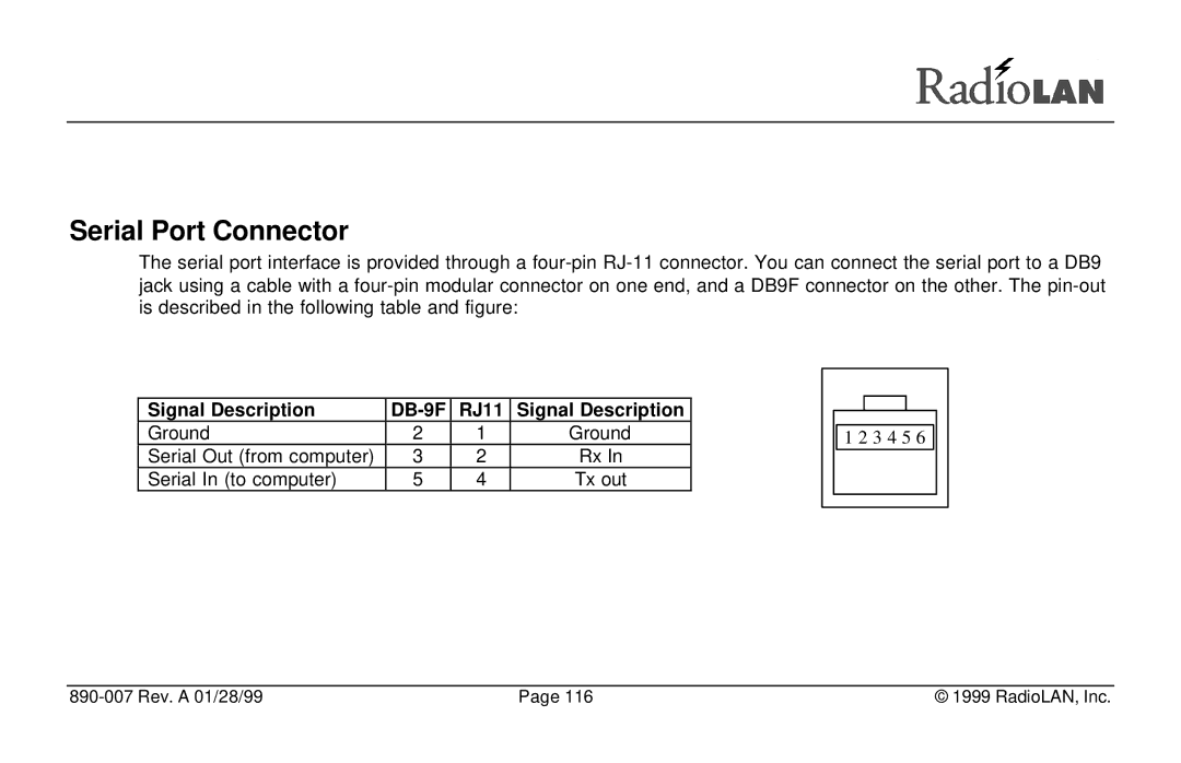
The serial port interface is provided through a
|
|
|
|
|
|
|
|
|
|
Signal Description | RJ11 | Signal Description |
|
|
|
|
|
| |
|
|
|
|
|
| ||||
Ground | 2 | 1 | Ground |
|
|
|
| ||
|
| 1 2 3 4 5 6 |
| ||||||
Serial Out (from computer) | 3 | 2 | Rx In |
|
|
|
|
|
|
|
|
|
|
|
| ||||
Serial In (to computer) | 5 | 4 | Tx out |
|
|
|
|
|
|
|
|
|
|
|
|
|
|
|
|
|
|
|
|
|
|
|
|
|
|
| Page 116 | © 1999 RadioLAN, Inc. |