Use a pencil to mark the brackets screw hole locations onto the surface upon which you will mount the CPU.
At the location’s screw holes, install any necessary anchoring devices. This is especially recommended when installing the CPU onto a
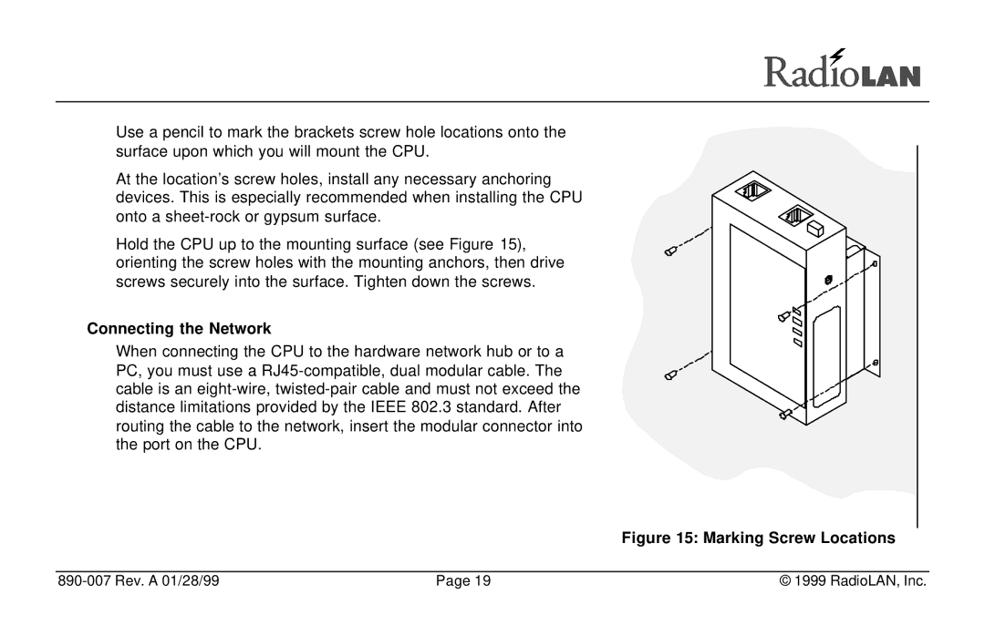
Hold the CPU up to the mounting surface (see Figure 15), orienting the screw holes with the mounting anchors, then drive screws securely into the surface. Tighten down the screws.
Connecting the Network
When connecting the CPU to the hardware network hub or to a PC, you must use a
Figure 15: Marking Screw Locations
| Page 19 | © 1999 RadioLAN, Inc. |