Section 5: Interface Specifications
5.14 STATUS 3
This transmission protocol responds the status from the printer using requested commands from the host and targets printer status control in the host.
Furthermore, the status is sent immediately after the request command has been received.
The data received cannot be guaranteed when Print data (ESC+"A" - ESC+"Z") is sent from the host under the following conditions:
1)When the printer is OFFLINE
2)When an error occurs in the printer
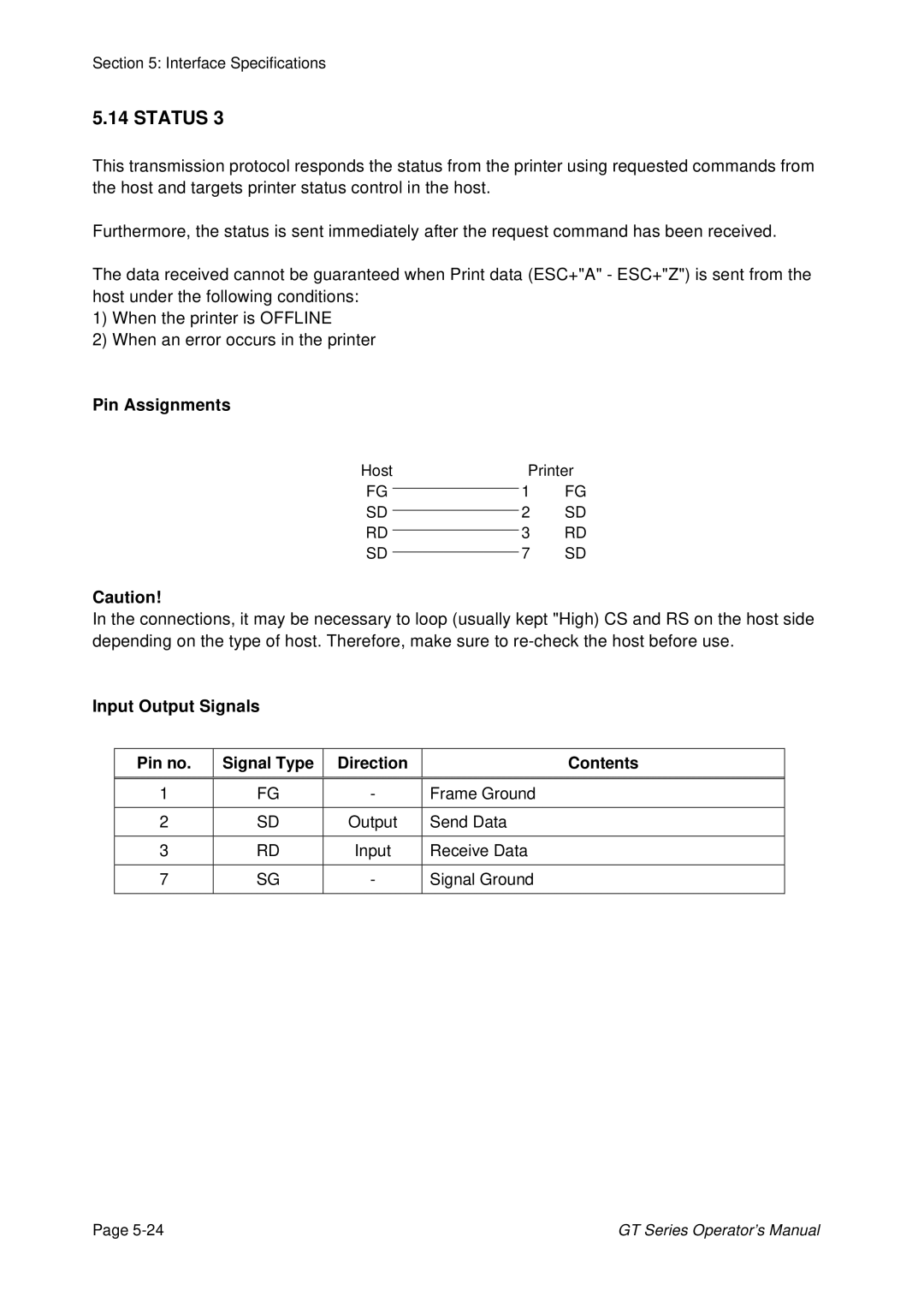
Pin Assignments
Host | Printer | ||
FG |
| 1 | FG |
| |||
SD |
| 2 | SD |
| |||
RD |
| 3 | RD |
| |||
SD |
| 7 | SD |
| |||
Caution!
In the connections, it may be necessary to loop (usually kept "High) CS and RS on the host side depending on the type of host. Therefore, make sure to
Input Output Signals
Pin no. | Signal Type | Direction | Contents |
|
|
|
|
1 | FG | - | Frame Ground |
|
|
|
|
2 | SD | Output | Send Data |
|
|
|
|
3 | RD | Input | Receive Data |
|
|
|
|
7 | SG | - | Signal Ground |
|
|
|
|
Page | GT Series Operator’s Manual |