Section 2: Installation
2.1.2 PARTS IDENTIFICATION (CONT’D)
IDENTIFYING THE MAIN PRINTER PARTS
View of Front Panel
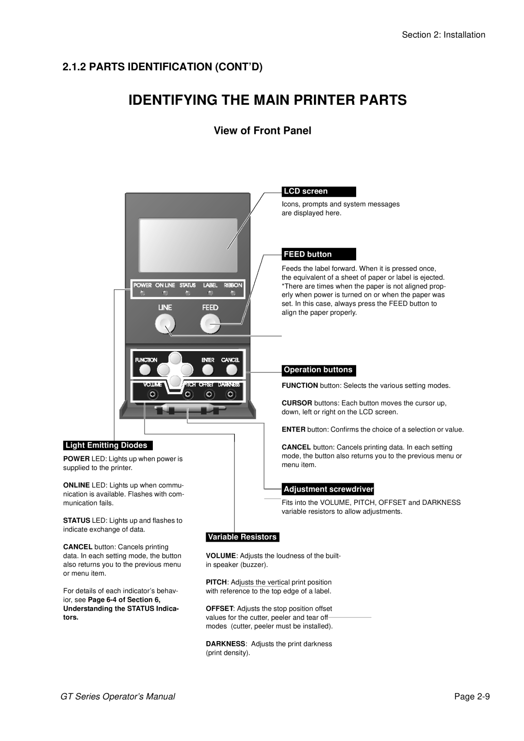
Light Emitting Diodes
POWER LED: Lights up when power is supplied to the printer.
ONLINE LED: Lights up when commu- nication is available. Flashes with com- munication fails.
STATUS LED: Lights up and flashes to indicate exchange of data.
LCD screen
Icons, prompts and system messages are displayed here.
FEED button
Feeds the label forward. When it is pressed once, the equivalent of a sheet of paper or label is ejected. *There are times when the paper is not aligned prop- erly when power is turned on or when the paper was set. In this case, always press the FEED button to align the paper properly.
Operation buttons
FUNCTION button: Selects the various setting modes.
CURSOR buttons: Each button moves the cursor up, down, left or right on the LCD screen.
ENTER button: Confirms the choice of a selection or value.
CANCEL button: Cancels printing data. In each setting mode, the button also returns you to the previous menu or menu item.
![]()
![]() Adjustment screwdriver
Adjustment screwdriver
Fits into the VOLUME, PITCH, OFFSET and DARKNESS variable resistors to allow adjustments.
| Variable Resistors |
|
CANCEL button: Cancels printing |
|
|
data. In each setting mode, the button | VOLUME: Adjusts the loudness of the built- | |
also returns you to the previous menu | in speaker (buzzer). | |
or menu item. |
|
|
| PITCH: Adjusts the vertical print position | |
For details of each indicator’s behav- ior, see Page
with reference to the top edge of a label.
Understanding the STATUS Indica- | OFFSET: Adjusts the stop position offset | |
tors. | values for the cutter, peeler and tear off |
|
| ||
| modes (cutter, peeler must be installed). | |
| DARKNESS: Adjusts the print darkness | |
| (print density). | |
GT Series Operator’s Manual | Page |
