Section 5: Interface Specifications
5.20 IEEE 1284 INTERFACE (CONT’D)
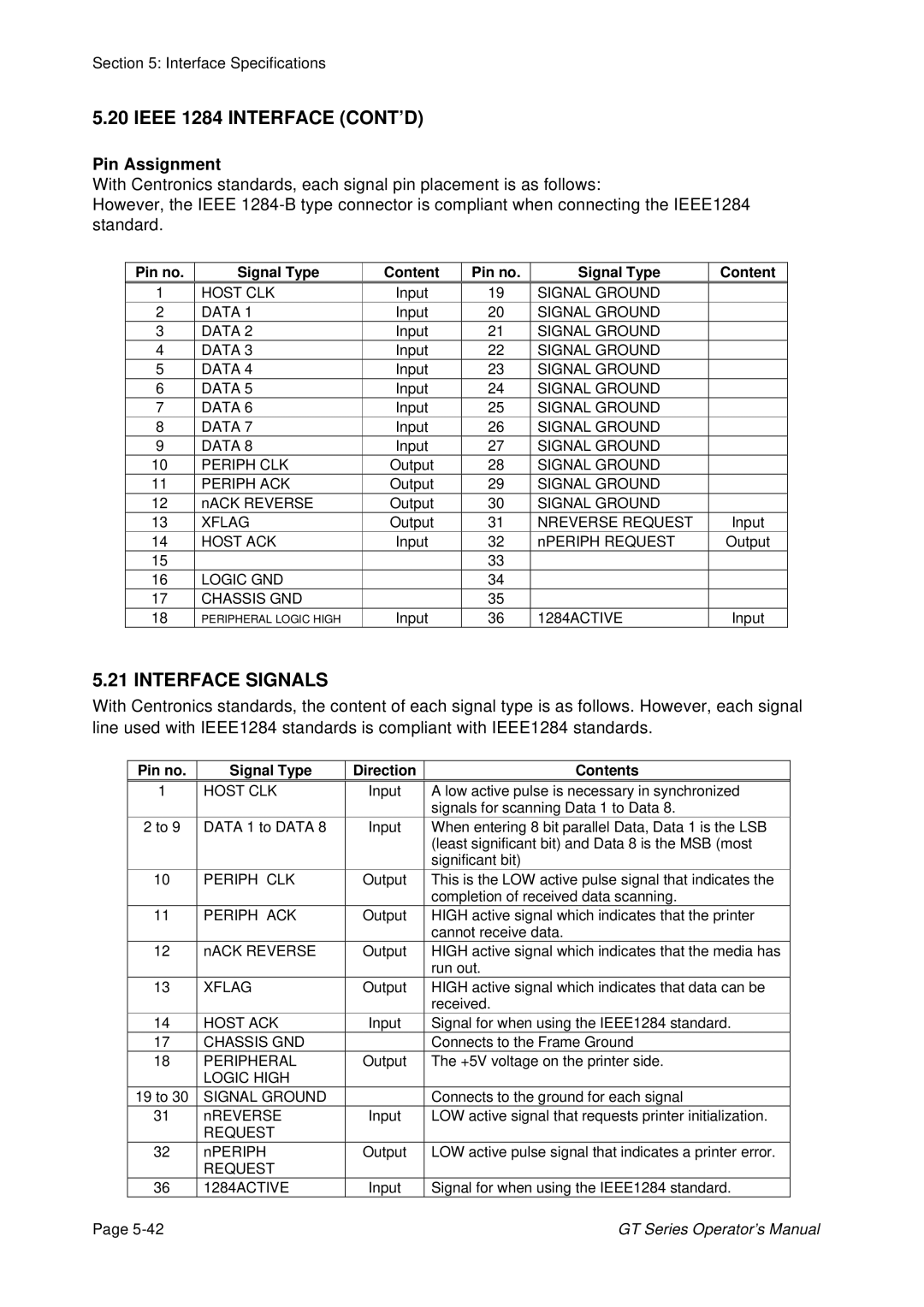
Pin Assignment
With Centronics standards, each signal pin placement is as follows:
However, the IEEE
Pin no.
Signal Type
Content
Pin no.
Signal Type
Content
1 | HOST CLK | Input | 19 | SIGNAL GROUND |
|
2 | DATA 1 | Input | 20 | SIGNAL GROUND |
|
3 | DATA 2 | Input | 21 | SIGNAL GROUND |
|
4 | DATA 3 | Input | 22 | SIGNAL GROUND |
|
5 | DATA 4 | Input | 23 | SIGNAL GROUND |
|
6 | DATA 5 | Input | 24 | SIGNAL GROUND |
|
7 | DATA 6 | Input | 25 | SIGNAL GROUND |
|
8 | DATA 7 | Input | 26 | SIGNAL GROUND |
|
9 | DATA 8 | Input | 27 | SIGNAL GROUND |
|
10 | PERIPH CLK | Output | 28 | SIGNAL GROUND |
|
11 | PERIPH ACK | Output | 29 | SIGNAL GROUND |
|
12 | nACK REVERSE | Output | 30 | SIGNAL GROUND |
|
13 | XFLAG | Output | 31 | NREVERSE REQUEST | Input |
14 | HOST ACK | Input | 32 | nPERIPH REQUEST | Output |
15 |
|
| 33 |
|
|
16 | LOGIC GND |
| 34 |
|
|
17 | CHASSIS GND |
| 35 |
|
|
18 | PERIPHERAL LOGIC HIGH | Input | 36 | 1284ACTIVE | Input |
5.21 INTERFACE SIGNALS
With Centronics standards, the content of each signal type is as follows. However, each signal line used with IEEE1284 standards is compliant with IEEE1284 standards.
Pin no. | Signal Type | Direction | Contents | |
1 | HOST CLK | Input | A low active pulse is necessary in synchronized | |
|
|
|
| signals for scanning Data 1 to Data 8. |
2 to 9 | DATA 1 to DATA 8 | Input | When entering 8 bit parallel Data, Data 1 is the LSB | |
|
|
|
| (least significant bit) and Data 8 is the MSB (most |
|
|
|
| significant bit) |
10 | PERIPH | CLK | Output | This is the LOW active pulse signal that indicates the |
|
|
|
| completion of received data scanning. |
11 | PERIPH | ACK | Output | HIGH active signal which indicates that the printer |
|
|
|
| cannot receive data. |
12 | nACK REVERSE | Output | HIGH active signal which indicates that the media has | |
|
|
|
| run out. |
13 | XFLAG |
| Output | HIGH active signal which indicates that data can be |
|
|
|
| received. |
14 | HOST ACK | Input | Signal for when using the IEEE1284 standard. | |
17 | CHASSIS GND |
| Connects to the Frame Ground | |
18 | PERIPHERAL | Output | The +5V voltage on the printer side. | |
| LOGIC HIGH |
|
| |
19 to 30 | SIGNAL GROUND |
| Connects to the ground for each signal | |
31 | nREVERSE | Input | LOW active signal that requests printer initialization. | |
| REQUEST |
|
| |
32 | nPERIPH |
| Output | LOW active pulse signal that indicates a printer error. |
| REQUEST |
|
| |
36 | 1284ACTIVE | Input | Signal for when using the IEEE1284 standard. | |
Page | GT Series Operator’s Manual |