Section 5: Interface Specifications
5.17 PARALLEL INTERFACE (CONT’D)
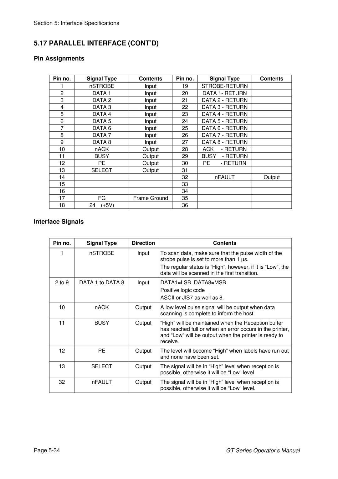
Pin Assignments
Pin no.
Signal Type
Contents
Pin no.
Signal Type
Contents
| 1 |
| nSTROBE | Input |
|
| 19 |
|
| |||||
| 2 |
| DATA 1 | Input |
|
| 20 | DATA 1- RETURN |
|
| ||||
| 3 |
| DATA 2 | Input |
|
| 21 | DATA 2 - RETURN |
|
| ||||
| 4 |
| DATA 3 | Input |
|
| 22 | DATA 3 - RETURN |
|
| ||||
| 5 |
| DATA 4 | Input |
|
| 23 | DATA 4 - RETURN |
|
| ||||
| 6 |
| DATA 5 | Input |
|
| 24 | DATA 5 - RETURN |
|
| ||||
| 7 |
| DATA 6 | Input |
|
| 25 | DATA 6 - RETURN |
|
| ||||
| 8 |
| DATA 7 | Input |
|
| 26 | DATA 7 - RETURN |
|
| ||||
| 9 |
| DATA 8 | Input |
|
| 27 | DATA 8 - RETURN |
|
| ||||
| 10 |
| nACK | Output |
|
| 28 | ACK | - RETURN |
|
| |||
| 11 |
| BUSY | Output |
|
| 29 | BUSY | - RETURN |
|
| |||
| 12 |
|
| PE | Output |
|
| 30 | PE | - RETURN |
|
| ||
| 13 |
| SELECT | Output |
|
| 31 |
|
|
|
| |||
| 14 |
|
|
|
|
|
|
| 32 | nFAULT |
| Output | ||
| 15 |
|
|
|
|
|
|
| 33 |
|
|
|
| |
| 16 |
|
|
|
|
|
|
| 34 |
|
|
|
| |
| 17 |
|
| FG | Frame Ground |
| 35 |
|
|
|
| |||
| 18 |
| 24 | (+5V) |
|
|
|
| 36 |
|
|
|
| |
Interface Signals |
|
|
|
|
|
|
|
|
|
|
| |||
|
|
|
|
|
|
|
|
|
|
| ||||
|
| Pin no. |
| Signal Type | Direction |
|
|
|
| Contents |
| |||
|
|
|
|
|
|
| ||||||||
| 1 |
| nSTROBE | Input |
| To scan data, make sure that the pulse width of the | ||||||||
|
|
|
|
|
|
|
| strobe pulse is set to more than 1 µs. |
| |||||
|
|
|
|
|
|
|
| The regular status is “High”, however, if it is “Low”, the | ||||||
|
|
|
|
|
|
|
| data will be scanned in the first transition. |
| |||||
|
|
|
|
|
|
|
| |||||||
|
| 2 to 9 | DATA 1 to DATA 8 | Input |
| DATA1=LSB DATA8=MSB |
| |||||||
|
|
|
|
|
|
|
| Positive logic code |
|
|
| |||
|
|
|
|
|
|
|
| ASCII or JIS7 as well as 8. |
| |||||
|
|
|
|
|
|
| ||||||||
| 10 |
| nACK | Output |
| A low level pulse signal will be output when data | ||||||||
|
|
|
|
|
|
|
| scanning is complete to inform the host. |
| |||||
|
|
|
|
|
|
| ||||||||
| 11 |
| BUSY | Output |
| “High” will be maintained when the Reception buffer | ||||||||
|
|
|
|
| Ω |
|
| has reached full or when an error occurs in the printer, | ||||||
|
|
|
|
|
|
| and “Low” will be output when the printer is ready to | |||||||
|
|
|
|
|
|
| receive. |
|
|
|
|
| ||
| 12 |
|
| PE | Output |
| The level will become “High” when labels have run out | |||||||
|
|
|
|
|
|
|
| and none have been set. |
|
|
| |||
|
|
|
|
|
|
| ||||||||
| 13 |
| SELECT | Output |
| The signal will be in “High” level when reception is | ||||||||
|
|
|
|
|
|
|
| possible, otherwise it will be “Low” level. |
| |||||
|
|
|
|
|
|
| ||||||||
| 32 |
| nFAULT | Output |
| The signal will be in “High” level when reception is | ||||||||
|
|
|
|
|
|
|
| possible, otherwise it will be “Low” level. |
| |||||
|
|
|
|
|
|
|
|
|
|
|
|
|
|
|
Page | GT Series Operator’s Manual |