Monaco Technical Reference | Spectrum Signal Processing |
Introduction
1.4.General Bus Architecture
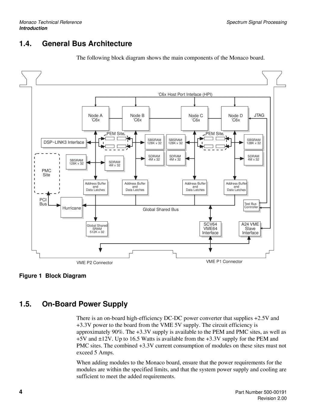
The following block diagram shows the main components of the Monaco board.
'C6x Host Port Inteface (HPI)
| Node A | Node B |
| Node C | Node D | JTAG |
| 'C6x | 'C6x |
| 'C6x | 'C6x |
|
| PEM Site |
|
| PEM Site |
|
|
DSP~LINK3 Interface |
| SBSRAM | SBSRAM |
|
| SBSRAM |
| 128K x 32 | 128K x 32 |
|
| 128K x 32 | |
|
| SDRAM | SDRAM |
|
| SDRAM |
SBSRAM | SDRAM | 4M x 32 | 4M x 32 |
|
| 4M x 32 |
128K x 32 |
|
|
|
|
| |
4M x 32 |
|
|
|
|
| |
|
|
|
|
|
| |
PMC |
|
|
|
|
|
|
Site |
|
|
|
|
|
|
| Address Buffer | Address Buffer |
| Address Buffer | Address Buffer | |
| and | and |
| and | and |
|
| Data Latches | Data Latches |
| Data Latches | Data Latches | |
PCI |
|
|
|
|
|
|
Bus |
|
|
|
|
| Test Bus |
Hurricane |
| Global Shared Bus |
|
| Controller | |
|
|
|
|
| ||
| Global Shared |
|
| SCV64 | A24 VME | |
| SRAM |
|
| VME64 |
| Slave |
| 512K x 32 |
|
| Interface | Interface | |
VME P2 Connector | VME P1 Connector |
Figure 1 Block Diagram
1.5.On-Board Power Supply
There is an
When adding modules to the Monaco board, ensure that the power requirements for the modules are within the specified limits, and that the system power supply and cooling are sufficient to meet the added requirements.
4 | Part Number |