Spectrum Signal Processing | Monaco Technical Reference |
| Processor Nodes |
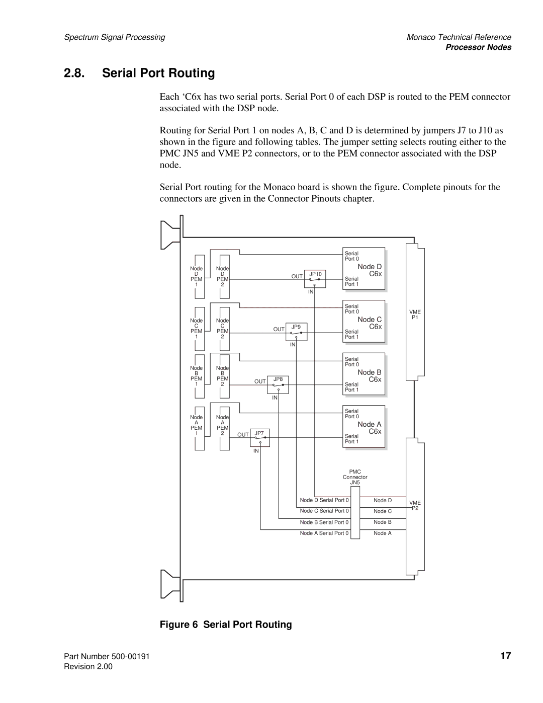
2.8.Serial Port Routing
Each ‘C6x has two serial ports. Serial Port 0 of each DSP is routed to the PEM connector associated with the DSP node.
Routing for Serial Port 1 on nodes A, B, C and D is determined by jumpers J7 to J10 as shown in the figure and following tables. The jumper setting selects routing either to the PMC JN5 and VME P2 connectors, or to the PEM connector associated with the DSP node.
Serial Port routing for the Monaco board is shown the figure. Complete pinouts for the connectors are given in the Connector Pinouts chapter.
|
|
|
| Serial |
|
|
|
|
| Port 0 |
|
Node | Node |
|
| Node D | |
D | D | OUT | JP10 | Serial | ‘C6x |
PEM | PEM |
|
| ||
|
|
| |||
1 | 2 |
|
| Port 1 |
|
|
|
| IN |
|
|
|
|
|
|
|
|
Node |
|
| Node | ||
C |
|
|
| C | |
PEM |
|
| PEM | ||
1 |
|
| 2 | ||
|
|
|
|
|
|
|
|
|
| ||
|
|
|
|
|
|
Node |
|
| Node | ||
B |
|
|
| B | |
PEM |
|
| PEM | ||
1 |
|
| 2 | ||
|
|
|
|
|
|
|
|
|
| ||
|
|
|
|
|
|
Node |
|
| Node | ||
A |
|
|
| A | |
PEM |
|
| PEM | ||
1 |
|
| 2 | ||
|
|
|
|
|
|
OUT JP9
IN
OUT JP8
IN
OUT | JP7 |
IN
Serial
Port 0
Node C ‘C6x
Serial
Port 1
Serial
Port 0
Node B ‘C6x
Serial
Port 1
Serial
Port 0
Node A ‘C6x
Serial
Port 1
VME
P1
PMC
Connector
JN5
Node D Serial Port 0 |
| Node D |
Node C Serial Port 0 |
| Node C |
Node B Serial Port 0 |
| Node B |
Node A Serial Port 0 |
| Node A |
|
|
|
VME
P2
Part Number
Figure 6 Serial Port Routing
17