Spectrum Signal Processing | Monaco Technical Reference |
| JTAG Debugging |
7 JTAG Debugging
The Monaco board supports JTAG
JTAG
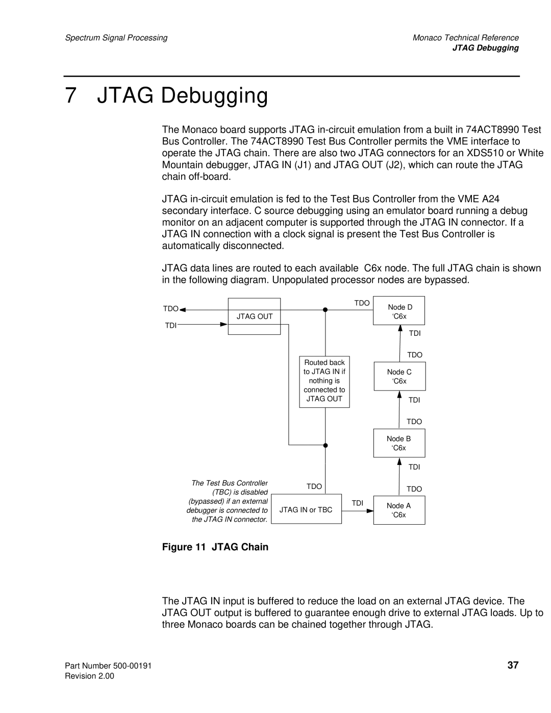
JTAG data lines are routed to each available ‘C6x node. The full JTAG chain is shown in the following diagram. Unpopulated processor nodes are bypassed.
TDO
TDO![]() JTAG OUT
JTAG OUT
TDI
Routed back to JTAG IN if nothing is connected to
JTAG OUT
The Test Bus Controller |
| TDO | ||
(TBC) is disabled |
| |||
|
|
|
| |
(bypassed) if an external |
|
|
| TDI |
| JTAG IN or TBC |
| ||
debugger is connected to |
|
|
| |
the JTAG IN connector. |
|
|
|
|
|
|
|
| |
Node D ‘C6x
TDI
TDO
Node C ‘C6x
TDI
TDO
Node B ‘C6x
TDI
TDO
Node A ‘C6x
Figure 11 JTAG Chain
The JTAG IN input is buffered to reduce the load on an external JTAG device. The JTAG OUT output is buffered to guarantee enough drive to external JTAG loads. Up to three Monaco boards can be chained together through JTAG.
Part Number | 37 |
Revision 2.00 |
|