Monaco Technical Reference | Spectrum Signal Processing |
Introduction
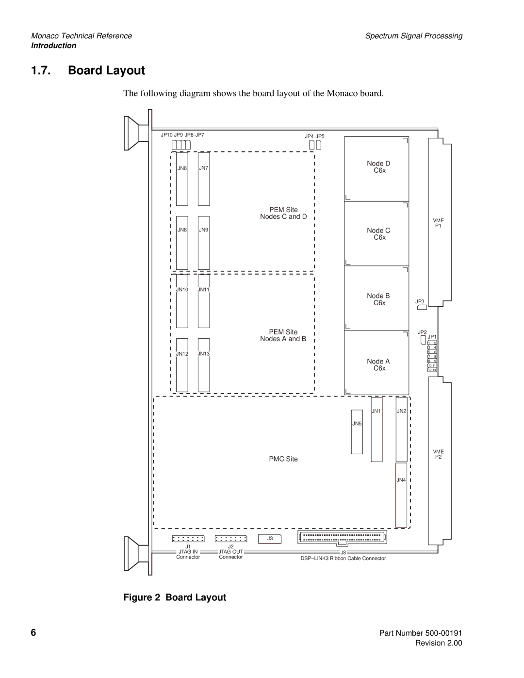
1.7.Board Layout
The following diagram shows the board layout of the Monaco board.
JP10 JP9 JP8 JP7 |
| JP4 JP5 |
|
| |
JN6 | JN7 |
| Node D |
|
|
| ‘C6x |
|
| ||
|
|
|
|
| |
|
| PEM Site |
|
|
|
|
| Nodes C and D |
| VME | |
|
|
|
|
| |
JN8 | JN9 |
| Node C |
| P1 |
|
|
| |||
|
|
| ‘C6x |
|
|
JN10 | JN11 |
| Node B |
|
|
|
|
| JP3 |
| |
|
|
| ‘C6x |
| |
|
| PEM Site |
| JP2 |
|
|
| Nodes A and B | JP1 | ||
|
| 1 | 2 | ||
|
|
|
| ||
|
|
|
| 3 | 4 |
JN12 | JN13 |
|
| 5 | 6 |
|
| 7 | 8 | ||
|
|
| Node A | ||
|
|
| 8 | 9 | |
|
|
| 10 11 | ||
|
|
| ‘C6x | ||
|
|
| 12 13 | ||
|
|
| JN1 | JN2 |
|
|
|
| JN5 |
|
|
|
|
|
|
| VME |
|
| PMC Site |
|
| P2 |
|
|
|
|
| |
|
|
|
| JN4 |
|
|
| J3 |
|
|
|
J1 |
| J2 |
|
|
|
JTAG IN |
| JTAG OUT | J8 |
|
|
Connector | Connector | DSP~LINK3 Ribbon Cable Connector |
|
| |
Figure 2 Board Layout
6 | Part Number |