Monaco Technical Reference | Spectrum Signal Processing |
DSP~LINK3 Interface |
|
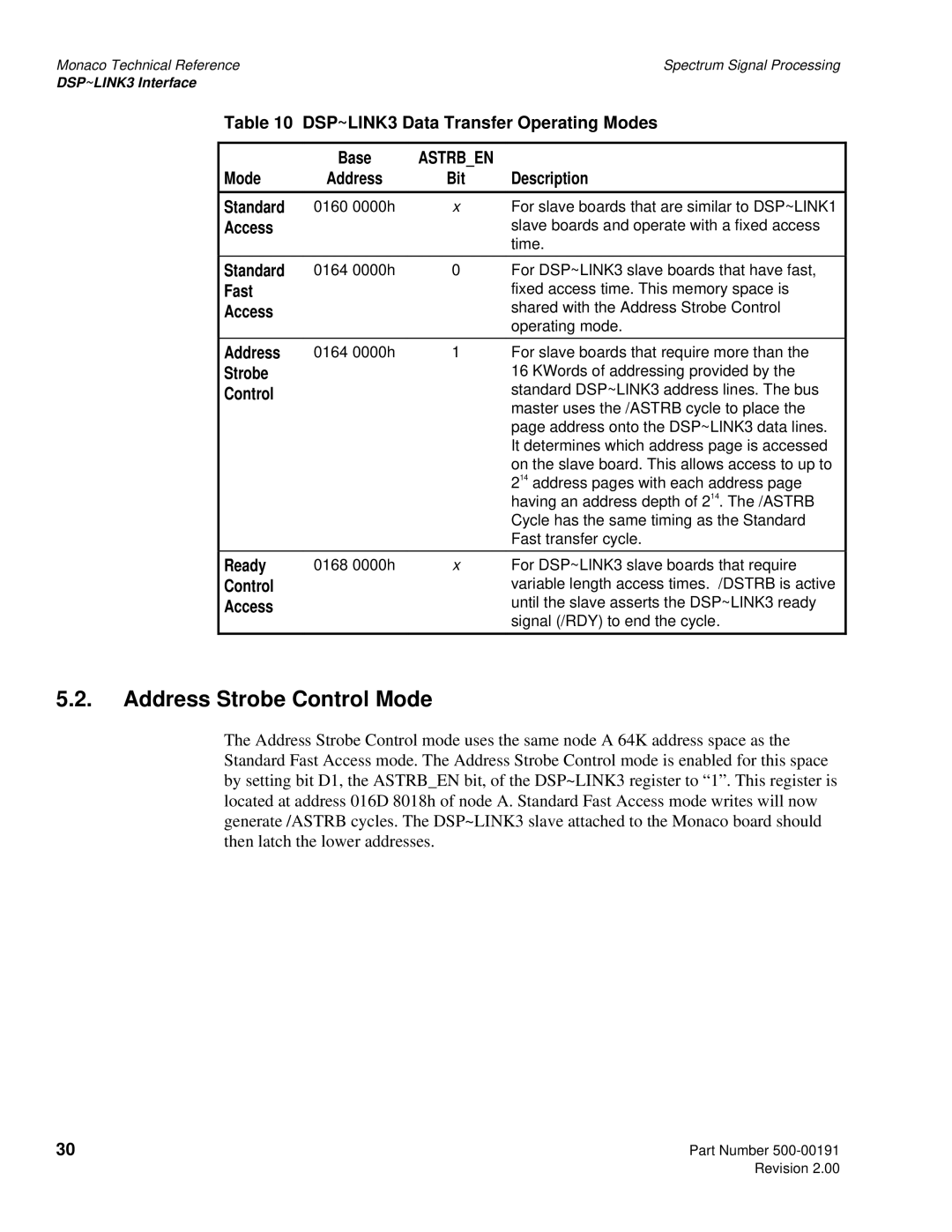
Table 10 DSP~LINK3 Data Transfer Operating Modes
| Base | ASTRB_EN |
|
Mode | Address | Bit | Description |
|
|
|
|
Standard | 0160 0000h | x | For slave boards that are similar to DSP~LINK1 |
Access |
|
| slave boards and operate with a fixed access |
|
|
| time. |
|
|
|
|
Standard | 0164 0000h | 0 | For DSP~LINK3 slave boards that have fast, |
Fast |
|
| fixed access time. This memory space is |
Access |
|
| shared with the Address Strobe Control |
|
|
| operating mode. |
Address | 0164 0000h | 1 | For slave boards that require more than the |
Strobe |
|
| 16 KWords of addressing provided by the |
Control |
|
| standard DSP~LINK3 address lines. The bus |
|
|
| master uses the /ASTRB cycle to place the |
|
|
| page address onto the DSP~LINK3 data lines. |
|
|
| It determines which address page is accessed |
|
|
| on the slave board. This allows access to up to |
|
|
| 214 address pages with each address page |
|
|
| having an address depth of 214. The /ASTRB |
|
|
| Cycle has the same timing as the Standard |
|
|
| Fast transfer cycle. |
|
|
|
|
Ready | 0168 0000h | x | For DSP~LINK3 slave boards that require |
Control |
|
| variable length access times. /DSTRB is active |
Access |
|
| until the slave asserts the DSP~LINK3 ready |
|
|
| signal (/RDY) to end the cycle. |
5.2.Address Strobe Control Mode
The Address Strobe Control mode uses the same node A 64K address space as the Standard Fast Access mode. The Address Strobe Control mode is enabled for this space by setting bit D1, the ASTRB_EN bit, of the DSP~LINK3 register to “1”. This register is located at address 016D 8018h of node A. Standard Fast Access mode writes will now generate /ASTRB cycles. The DSP~LINK3 slave attached to the Monaco board should then latch the lower addresses.
30 | Part Number |
| Revision 2.00 |