Sun Microsystems CP3260 manual A.4.1.1 Ethernet Port, A.4.1.2 Dual USB Port, Activity LED yellow

Models: CP3260

1 144
Download 144 pages 25.13 Kb
Page 122
Image 122
A.4.1.1 Ethernet Port

A.4.1.1 Ethernet Port

The Ethernet connector is a
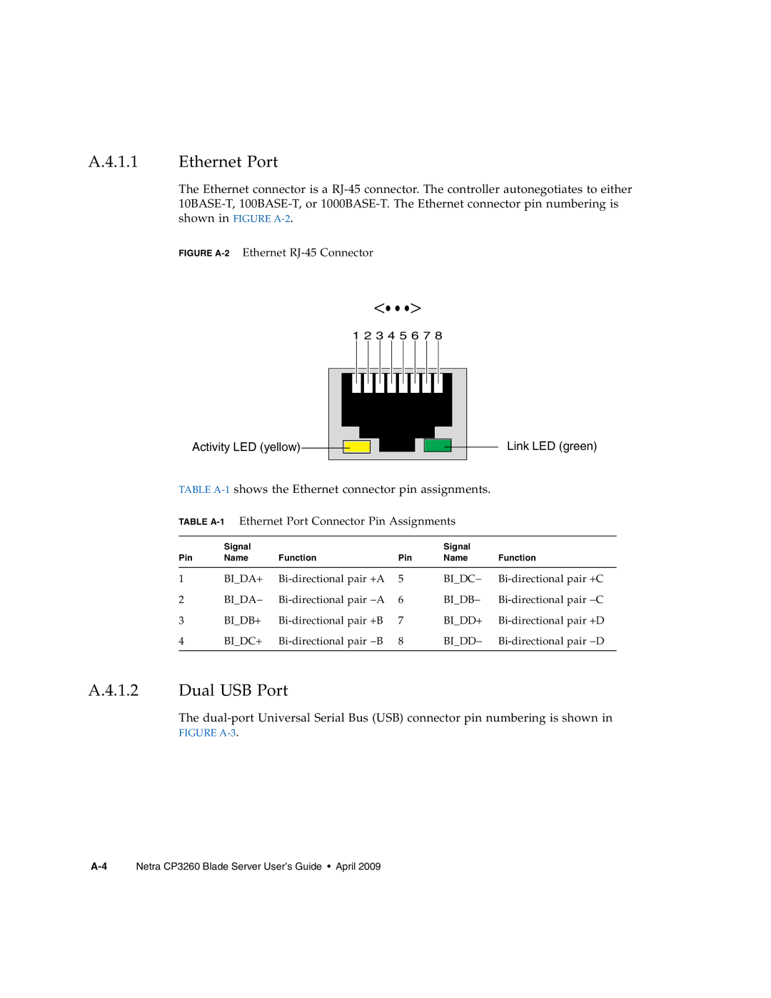
 RJ-45 connector. The controller autonegotiates to either 10BASE-T,100BASE-T, or 1000BASE-T. The Ethernet connector pin numbering is shown in FIGURE A-2.

FIGURE A-2Ethernet RJ-45 Connector

<...>

1 2 3 4 5 6 7 8

Activity LED (yellow)Activity LED (yellow)Link LED (green)

Link LED (green)

TABLE A-1shows the Ethernet connector pin assignments.

TABLE A-1Ethernet Port Connector Pin Assignments


Signal


Signal


Pin

Name

Function

Pin

Name

Function


1

BI_DA+

Bi-directional pair +A

5

BI_DC−

Bi-directional pair +C

2

BI_DA−

Bi-directional pair −A

6

BI_DB−

Bi-directional pair −C

3

BI_DB+

Bi-directional pair +B

7

BI_DD+

Bi-directional pair +D

4

BI_DC+

Bi-directional pair −B

8

BI_DD−

Bi-directional pair −D


A.4.1.2 Dual USB Port

The dual-port Universal Serial Bus (USB) connector pin numbering is shown in FIGURE A-3.

A-4Netra CP3260 Blade Server User’s Guide • April 2009

Page 122
Image 122
Sun Microsystems CP3260 manual A.4.1.1 Ethernet Port, A.4.1.2 Dual USB Port, Activity LED yellow, Link LED green