April 2009, Revision
Sun Netra CP3260 Blade Server User’s Guide
Sun Microsystems, Inc
Please Recycle
Preface 1. Introduction
Contents
2. Hardware Installation
iv Netra CP3260 Blade Server User’s Guide April
3. Software Installation
4. Firmware and Blade Server Management
5. Hardware Functional Descriptions
probe-scsi and probe-scsi-all Commands
4.3.3.4 Using watch-net and watch-net-all Commands to
vi Netra CP3260 Blade Server User’s Guide April
Get RTM Status Command
Get Version Command
A. Physical Characteristics
B. Sun OEM IPMI Commands B-1
Solaris OS Graceful Shutdown Commands B-4
Send Sensor State Command B-5
Index
Index-1
Figures
Zone 2 Connectors A-9
Power Distribution Connector Zone 1 P10 A-7
Zone 3 Signal Connectors
Zone 3 Power Connector
Ethernet Port Connector Pin Assignments
Tables
CPU Temperature Alarms
Get RTM Status Command Data Bytes
Get Version Command Data Bytes B-2
Send Sensor State Command Data Bytes
TABLE B-1
How This Document Is Organized
Preface
Shell Prompts
Using UNIX Commands
Related Documentation
Typographic Conventions
Third-Party Web Sites
Documentation, Support, and Training
Sun Netra CP32x0 SAS Storage
Advanced Rear Transition Module
Sun Netra CP3260 Blade Server User’s Guide, part number
Sun Welcomes Your Comments
xviii Sun Netra CP3260 Blade Server User’s Guide April
Section 1.3, “System Configurations” on page
Section 1.1, “Overview” on page Section 1.2, “Features” on page
Section 1.7, “Technical Support and Warranty” on page
Introduction
1.2 Features
Chapter 1 Introduction
FeatureDescription
1-4 Netra CP3260 Blade Server User’s Guide April
FIGURE 1-1 Netra CP3260 Blade Server Front Panel
Chapter 1 Introduction
FIGURE 1-2 Netra CP3260 Blade Server Top View
1-6 Netra CP3260 Blade Server User’s Guide April
⑤ ④ ③ ② ① ⑦
8 Hot-Swap switch and bottom latch
1 Top latch 2 Out of Service LED yellow
1 Zone 1 power connector 2 Zone 2 signal connectors
3 Zone 3 RTM signal connectors 4 Zone 3 ARTM power connector
1-8 Netra CP3260 Blade Server User’s Guide April
1.3 System Configurations
Chapter 1 Introduction
FIGURE 1-3 Netra CP3260 Blade Server in an ATCA Shelf Enclosure
kless client that boots through network from a remote server
⑤ ⑥ ⑦
Ethernet
1-10 Netra CP3260 Blade Server User’s Guide April
1 Remote server 2 Sun Netra CP32X0 Advanced RTM installed from rear
1.4 Advanced Rear Transition Modules
6 Sun Netra CP3260 blade server installed from front
3 Serial connection 4 Console terminal 5 Ethernet connection RJ-45
1-12 Netra CP3260 Blade Server User’s Guide April
①② ③
FIGURE 1-4 Netra CP3260 Blade Server, Midplane, and Netra CP32x0 ARTM
3 ATCA chassis midplane
TABLE 1-2 I/O Configurations
1 Sun Netra CP3260 blade server 2 Sun Netra CP32X0 ARTM
1.6.1 Hardware Requirements and Options
1.5 Hot-Swap Support
1.6 System Requirements and Options
http//docs.sun.com/app/docs/prod/netra.brds
1.7 Technical Support and Warranty
1.6.2 Software Requirements
1.7.1 Part Number, Serial Number, and Revision Number Identification
Chapter 1 Introduction
FIGURE 1-5 Netra CP3260 Blade Server Barcode Labeling
1-18 Netra CP3260 Blade Server User’s Guide April
2.1 Equipment and Operator Safety
Hardware Installation
Section 2.1, “Equipment and Operator Safety” on page
Section 2.3, “Preparing for the Installation” on page
Use an antistatic wrist strap when
2.3.1 Checking Power, Thermal, Environmental, and Space Requirements
2.3 Preparing for the Installation
2.2 Materials and Tools Required
page
2.4 Installation Procedure Summary
2.5.1 Adding or Replacing FB-DIMM Memory Modules
2.5 Configuring On-Board Hardware
2-6 Netra CP3260 Blade Server User’s Guide April
FIGURE 2-1 FB-DIMM Memory Locations
Chapter 2 Hardware Installation
2-8 Netra CP3260 Blade Server User’s Guide April
FB0B
2.5.1.1 To Remove FB-DIMM Memory Modules
FIGURE 2-2 Removing an FB-DIMM Memory Module
2.5.1.2 To Install FB-DIMM Memory Modules
1. Locate the FB-DIMM connectors on the Netra CP3260 blade server
2.5.2 Adding or Replacing Compact Flash Card
2-14 Netra CP3260 Blade Server User’s Guide April
2.5.3 Adding or Replacing TOD Clock Battery
1 Compact Flash connector
1. Remove the FB-DIMM closest to the front panel
2-16 Netra CP3260 Blade Server User’s Guide April
FIGURE 2-5 TOD Battery Location
Chapter 2 Hardware Installation
2-18 Netra CP3260 Blade Server User’s Guide April
2.6 Installing an Advanced Rear Transition Module Optional
FIGURE 2-6 Installing a Netra CP32X0 ARTM
② ① ③
Chapter 2 Hardware Installation
1 Netra CP3260 blade server 2 Netra CP32X0 ARTM
2.7 Installing the Netra CP3260 Blade Server
Chapter 2 Hardware Installation
FIGURE 2-7 Installing Blade Server Into Chassis Slot
2-22 Netra CP3260 Blade Server User’s Guide April
2.8 Connecting External I/O Cables
FIGURE 2-8 Netra CP3260 Blade Server Latches and Locking Screws
Information on connecting each of these cables follows
2.9 Hot-Swapping the Netra CP3260 Blade Server
FIGURE 2-9 Hot-Swap Latch and Hot-Swap LED
Chapter 2 Hardware Installation
2-26 Netra CP3260 Blade Server User’s Guide April
Section 3.3, “Installing as a Diskless Clients” on page
Software Installation
Section 3.4, “Firmware Updates” on page
Section 3.5, “Configuring for 1-GbE or 10-GbE Switches” on page
CODE EXAMPLE 3-2 Zone 3 Connectivity Both nxge Ports
3.2 Configuring Payload OS NIU Driver for Multiplexing to Zones 2 and
CODE EXAMPLE 3-1 Zone 2 Connectivity Both nxge Ports
Chapter 3 Software Installation
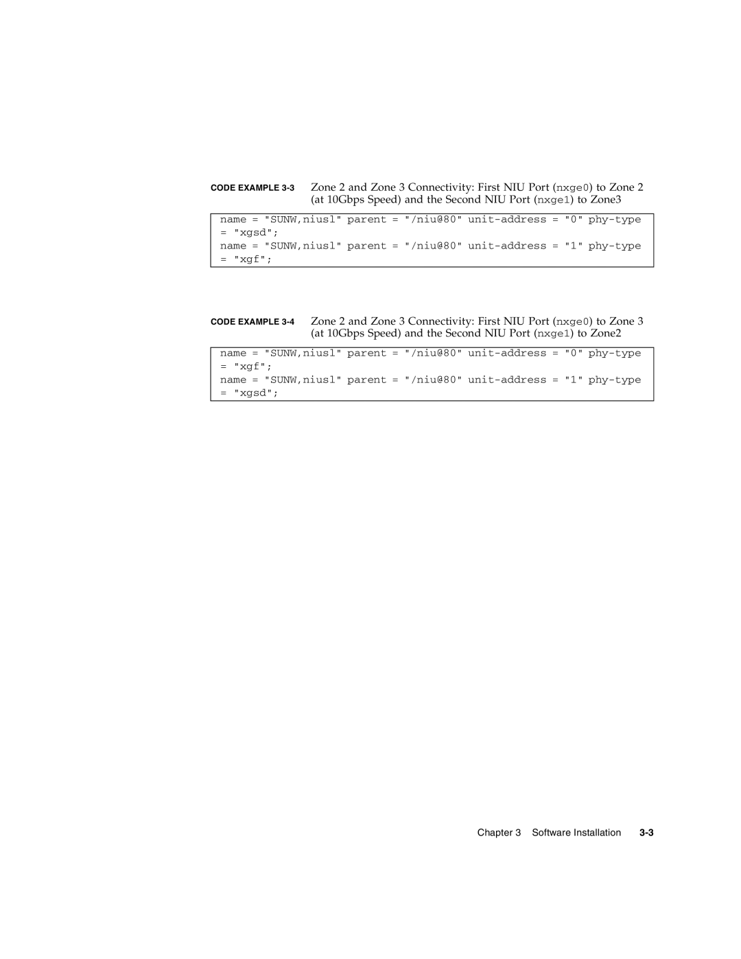
http//docs.sun.com/app/docs/prod/solaris
3.3 Installing as a Diskless Clients
3.3.1 Creating a Boot Server for Diskless Clients
3.3.2 Adding a Diskless Client
rootpassword = rootpassword imagedirectory = /export/install
locale = enUS
4. Download and install additional patches
ethernetaddress = 802022b3aa
ipaddress =
hostname = clienthost
swapsize =
6. Boot the diskless client
timezone = US/Pacific locale = enUS nameservice = NIS
3.3.3 Determining Local Network IP Addresses and Host Names
http//docs.sun.com/app/docs/prod/netra.brds
3.4 Firmware Updates
3.5 Configuring for 1-GbE or 10-GbE Switches
3.6 Downloading and Installing SunVTS Software
3.7 Formatting the Optional Compact Flash Card
Section 4.3, “OpenBoot Firmware” on page
Section 4.2, “Power-On Self-Test Diagnostics” on page
Section 4.4, “Error Handling Summary” on page
Section 4.5, “Automatic System Recovery” on page
http//docs.sun.com/app/docs/prod/n900.srvr#hic
4.1 System Firmware
4.2.1 POST Test Coverage
4.2 Power-On Self-Test Diagnostics
4.2.2 POST Diagnostic and Error Message Format
4.3 OpenBoot Firmware
TABLE 4-1 Ways of Accessing the ok Prompt
4.3.1 Getting to the ok Prompt
probe-scsi and probe-scsi-all probe-ide show-devs
4.3.2 Auto-Boot Options
4.3.3 OpenBoot Commands
0 ok probe-scsi-all
4.3.3.1 probe-scsi and probe-scsi-all Commands
4.3.3.3 show-devs Command
4.3.3.2 probe-ide Command
cpu@37 cpu@36 cpu@35 cpu@34 cpu@33 cpu@32 cpu@31 cpu@30 cpu@2f cpu@2e
cpu@8 cpu@7 cpu@6 cpu@5 cpu@4 cpu@3 cpu@2 cpu@1
1000 Mbps full duplex Link up Looking for Ethernet Packets
0 ok watch-net
‘.’ is a Good Packet. ‘X’ is a Bad Packet Type any key to stop
‘.’ is a Good Packet. ‘X’ is a Bad Packet. Type any key to stop
diag-switch? is false
4.3.4 OpenBoot Configuration Variables
is false
If false
use-nvramrc? is true
string. network-boot-arguments can
protocol
key=value
security-mode is not none never
4.3.4.1 Viewing and Setting OpenBoot Configuration Variables
Halt the server to display the ok prompt
0 ok printenv
4.4 Error Handling Summary
4.5 Automatic System Recovery
4.5.1.2 To Disable Automatic System Recovery
4.5.1 Enabling and Disabling Automatic System Recovery
4.5.1.1 To Enable Automatic System Recovery
TABLE 4-3 Network Device Aliases
4.6 Network Device Aliases
Condition
connected ok configured bridge/fhs
4.7 Retrieving Device Information
console serial, 6f00000154 rtc obp-device, 6f00000161
pci pciex, 6f0000050e pci pciex, 6f00000533
network network, 6f00000804 network network, 6f00000814
L2BANK7 other, 6f00000cda BR0 other, 6f00000ce0 CH0 other, 6f00000ce6
CH0 other, 6f00000e4e D0 module, 6f00000e54 R0 unknown, 6f00000e5f
IMMU other, 6f00000f86 DMMU other, 6f00000f8c CORE5 other, 6f00000f92
P24 other, 6f000010a0 P25 other, 6f000010a6 P26 other, 6f000010ac
4.8 Multiplexing to Zones 2 and
Be aware of the following possible issues when multiplexing zones
5.1 Hardware Architecture
Hardware Functional Descriptions
Section 5.1, “Hardware Architecture” on page
Section 5.2, “Hardware Modules” on page
POWER PC MPC885 66MHz
5.1.1 UltraSPARC T2 Processor and Memory
5-2 Netra CP3260 Blade Server User’s Guide April
Flash
5.1.2 I/O
5.1.5 Power PC
5.1.3 Base and Fabric Interfaces
5.1.4 Additional I/O
5.2.1 UltraSPARC T2 Processor
5.2 Hardware Modules
5.1.6 ARTM Support
Chapter 5 Hardware Functional Descriptions
FIGURE 5-2 UltraSPARC T2 Multicore Processor Block Diagram
5-6 Netra CP3260 Blade Server User’s Guide April
UltraSPARC T2
5.2.1.1 Electronic Fuse
SPARC
SPARC
5.2.1.3 L2 Cache
5.2.1.2 Cores
5.2.1.4 Memory Controller
5.2.1.5 I/O Interface
5.2.3 I/O Subsystem
5.2.2 Memory Subsystem
5.2.2.1 Memory Capacity
5.2.2.2 Memory Speed
ARTM Power and Management
5.2.3.1 PCI Express Switch
5.2.3.2 Base Interface
5.2.3.3 Fabric Interface
5.2.5 Front Panel I/O
5.2.4 Other ARTM Interfaces
5.2.4.1 Serial Ports
5.2.4.2 Ethernet Management Port
5.2.6 Compact Flash Socket
5.2.7 Service Processor MPC885
5.2.5.3 Dual USB Ports
5.2.7.1 Field-Programmable Gate Array
5.2.8 Intelligent Platform Management Controller
5.2.8.2 Interface to the PPC
5.2.8.1 Intelligent Platform Management Bus
5.2.8.3 IPMB-L Interface
5.2.8.4 ATCA Hot-Swap Latch
5.2.8.5 LEDs
5.2.8.6 Power Control
5.2.8.7 System Monitor ADM1026 and Thresholds
Voltage Monitoring
TABLE 5-1 Voltage Sensor Thresholds
Temperature Monitoring
TABLE 5-2 CPU Temperature Alarms
5.2.8.8 FRUID PROMs
5.2.9 I/O Subsystem Resets
5.2.11 TOD Clock Battery
5.2.10 ATCA Power Module −48V to
Section A.4, “Connectors and Pinout” on page A-3
Physical Characteristics
A.1 Form Factor
A.2 Layout
A-2 Netra CP3260 Blade Server User’s Guide April
② ③ ⑥ ⑤
FIGURE A-1 Netra CP3260 Blade Server Layout
A.3.1 Visual Indicators
A.4 Connectors and Pinout
A.4.1 Front Panel Connectors
A.3 Front Panel
A.4.1.2 Dual USB Port
A.4.1.1 Ethernet Port
Activity LED yellow
Link LED green
Serial Port
For USB connector signals, see TABLE A-2
A.4.1.3
I0I0I
A.4.2 Compact Flash Connector
A.4.3 Midplane Power Connector Zone
FIGURE A-5 Power Distribution Connector Zone 1 P10
TABLE A-4 lists the power connector pin assignments
TABLE A-4 Power Distribution Connector Pin Assignments
FIGURE A-5 shows the pin assignments
A.4.4 Data Transport Connector Zone
Appendix A Physical Characteristics
TABLE A-5 gives the Zone 2 J23 connector pin assignments
TABLE A-6 gives the Zone 2 J20 connector pin assignments
A.4.5 Sun Netra ARTM Connectors Zone
TABLE A-8 gives the Zone 3 J32 connector signals and pin assignments
TABLE A-7 gives the Zone 3 J31 connector signals and pin assignments
TABLE A-7 Zone 3 J31 Connector Pin Assignments
TABLE A-8 Zone 3 J32 Connector Pin Assignments
n Pow Con
TABLE A-9 gives the Zone 3 J33 connector signals and pin assignments
TABLE A-10 Zone 3 Power Connector Pin Assignments
A.4.6 TOD Clock Battery Holder
1 TOD battery location
FIGURE A-9 TOD Battery Location
2 TOD clock battery location with FB-DIMM removed
A-14 Netra CP3260 Blade Server User’s Guide April
Section B.1, “Get Version Command” on page B-2
Sun OEM IPMI Commands
Section B.2, “Get RTM Status Command” on page B-3
Section B.3, “Solaris OS Graceful Shutdown Commands” on page B-4
Get Version
B.1 Get Version Command
Example Terminal Mode
B.2 Get RTM Status Command
Example Terminal Mode
B.3 Solaris OS Graceful Shutdown Commands
Netra CT 900 Software Developer’s Guide 819-1178 for IPMI commands
B.4 Send Sensor State Command
B-6 Netra CP3260 Blade Server User’s Guide April
TABLE B-3 Send Sensor State Command Data Bytes Continued
B-8 Netra CP3260 Blade Server User’s Guide April
Index
Page