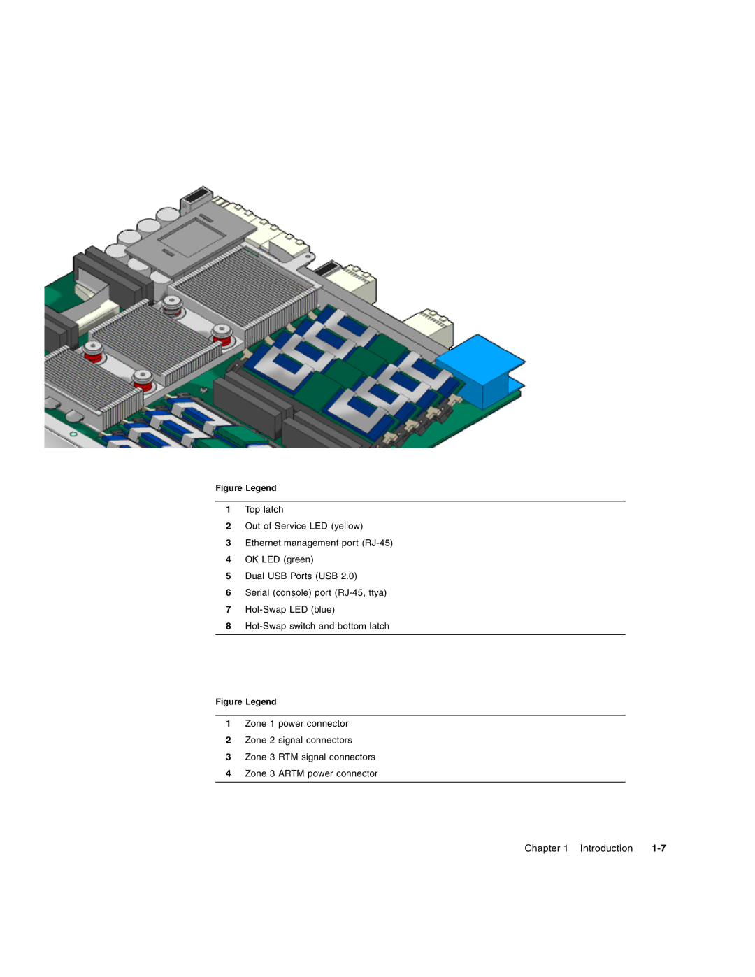
Figure Legend
1Top latch
2Out of Service LED (yellow)
3Ethernet management port
4OK LED (green)
5Dual USB Ports (USB 2.0)
6Serial (console) port
7
8
Figure Legend
1Zone 1 power connector
2Zone 2 signal connectors
3Zone 3 RTM signal connectors
4Zone 3 ARTM power connector
Chapter 1 Introduction |
